
Product Overview
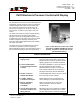
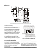
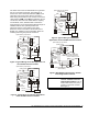

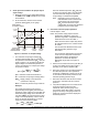
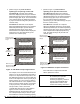
Table Of Contents

2 P—
P470 Electronic Pressure Control with Display Product/Technical Bulletin
A
pplication
IMPORTANT: The P470 Electronic Pressure
Control is intended to control
equipment under normal
operating conditions. Where
failure or malfunction of the P470
control could lead to an abnormal
operating condition that could
cause personal injury or damage
to the equipment or other
property, other devices (limit or
safety controls) or systems
(alarm or supervisory) intended
to warn of, or protect against
failure or malfunction of the P470
control must be incorporated into
and maintained as part of the
control system.
FCC Compliance Statement
This device complies with Part 15 of the FCC Rules.
Operation is subject to the following two conditions:
(1) this device may not cause harmful interference,
and (2) this device must accept any interference that
may cause undesired operation.
This equipment has been tested and found to comply
with the limits for a Class A digital device pursuant to
Part 15 of FCC rules. These limits are designed to
provide reasonable protection against harmful
interference when this equipment is operated in a
commercial environment. This equipment generates,
uses, and can radiate radio frequency energy and, if
not installed and used in accordance with the
instruction manual, may cause harmful interference to
radio communications. Operation of this equipment in
a residential area is likely to cause harmful
interference, in which case the user will be required to
correct the interference at his or her own expense.
Application Options
The P470 Electronic Pressure Control with Display is
designed for On/Off control (direct or pilot duty) of
refrigeration and HVAC loads based on system
pressure.
The P470 control’s total setpoint range is 0 to 750 psi.
The available operating ranges are: 0 to 100 psi,
0 to 500 psi, and 50 to 750 psi, depending on which
P399 transducer is wired to the control. See Table 1
for more information.
Note: Each of the P470 control’s three field
selectable, operating pressure ranges require
specific P399 transducer models to operate
properly. See Table 1 for more information.
The P399 transducer and P470 pressure control also
may be used on other non-corrosive fluid applications,
as well as ammonia applications.
The P470 control may replace a variety of
electromechanical pressure controls, and provides a
clear LCD display of the controlled equipment
pressure. The transducer may be mounted up to
100 ft (30.5m) away from the control using 3-wire
shielded cable, providing greater installation versatility,
and eliminating many of the constraints of capillary
tubes found on electro-mechanical pressure controls.
Up to four P470 controls may be wired to a single
P399 transducer on applications where the sensed
pressure may control difference functions. For
example, a high-pressure control and condenser fan
cycling control can use a common transducer to sense
high-side pressure, or four low-pressure controls may
be connected to a single transducer on the suction
manifold to stage four compressors on a refrigeration
rack. No more than four P470 controls should be wired
to one transducer. See Figure 7.
O
peration Overview
The P470 control uses a P399 Electronic Pressure
Transducer to sense system pressure. The control’s
operating pressure range depends on the transducer
model selected and the position of the pressure range
jumpers. See
Positioning the Jumpers
and Table 1.
The P399 transducer is mounted to a pressure tap
point on the refrigerant system. The transducer
generates a 0.5 to 4.5 VDC signal that the P470
pressure control converts to a psi value. See the
P399 Electronic Pressure Transducer
Product/Technical Bulletin (LIT-125515)
.
The sensed psi value is refreshed every two seconds
and displayed on the Liquid Crystal Display (LCD),
along with other control status information, during
normal operation. See Figure 3.
When the pressure at the transducer reaches the
cut-in setpoint the output relay is energized, the
front-panel LED lights, the Normally Open (N.O.)
contacts close and the Normally Closed (N.C.)
contacts open. When the cutout setpoint is reached
the output relay is de-energized, the LED goes off, and
the contacts return to their normal positions.