
Product Overview
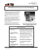
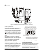
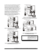

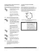
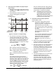
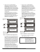
Table Of Contents

4 P—
P470 Electronic Pressure Control with Display Product/Technical Bulletin
When the cut-in and cutout values are established, the
P470 control automatically determines the control
operation and displays either an Open-high (
) or
Open-low (
) icon in the lower right of the LCD during
normal operation. See Figure 3.
The cut-in (
ci1
) and cutout (
co1
) values establish the
primary setpoints (
S1
). A secondary set (
S2
) of cut-in
(
ci2
) and cutout (
co2
) values may be also be set. The
S2
setpoints are enabled by a user-supplied Single-
Pole, Single-Throw (SPST) switching device such as a
control-clock or temperature control. See
Secondary
Cut-in and Cutout Setpoints
for instructions
.
Anti-Short Cycle Delay
establishes the minimum time
that the controlled equipment remains off before
starting again. The anti-short cycle delay activates
when the output relay de-energizes. The delay does
not allow the output relay to re-energize until the
user-set delay time has elapsed. When the delay is
activated the LCD flashes (alternately) the sensed
pressure value and
A
x
, where
x
is the number of
minutes of remaining delay time. The anti-short cycle
delay may be programmed for 0 to 9 minutes in
1-minute increments.
Notes:
A 0
indicates that the control is in the final
minute of the delay sequence.
Any power interruption to the control also
activates the anti-short cycle delay.
Secondary Cut-in and Cutout Setpoints
establish a
second set of cut-in and cutout values, which are
enabled when a circuit is closed between the binary
input terminals (
SP2
and
COM
) on the upper terminal
block (
TB3
). When the secondary setpoints are
enabled,
S2
is displayed instead of
S1
in the upper
right corner of the LCD. See Figure 3.
Settings Established by Jumper Position
Two of the P470 control settings are established by
positioning jumpers inside the control. These
parameters are explained below. For instructions on
how to position the jumpers, see
Positioning the
Jumpers
in the
Adjustments
section.
Pressure Range Jumper
positions establish the
pressure range that the P470 control operates in. Each
of the three pressure ranges requires a P399
transducer with a matching range. See Table 1 for
transducer model and pressure range information.
The pressure range jumpers may be positioned to
operate the control in a 0-100, 0-500, or 50-750 psi
range. See
Positioning the Jumpers
and Table 1.
Touchpad Lock
Jumper
position establishes if the
front panel may be used to adjust the control or not.
Locking out the touchpad helps deter tampering or
accidental changes to the established setpoints.
Note: The P470 control settings are “non-volatile”
and remain in the control’s memory during
power interruptions.
M
ounting and Wiring
!
WARNING:
Risk of Electrical Shock.
To avoid the risk of electrical
shock or damage to equipment,
disconnect all power sources to
the control before wiring any
connections.
Note: When mounting the P470 control to rigid
conduit, attach the hub to the conduit before
securing the hub to the control enclosure.
The P470 control has a NEMA 1 plastic enclosure with
four key-slot mounting holes on the back for surface
mounting. The mounting hole pattern on the P470
control is identical to the System 350
modules and
many other Johnson Control/PENN controls. The P470
control may also be mounted on 35 mm DIN rail. See
Dimensions
section. The P470 control is not position
sensitive but should be mounted for convenient wiring,
setup, and adjustment.
Observe the following guidelines and refer to the
wiring diagrams when wiring the control.
See Figures 4, 5, 6, and 7.
•
All wiring must conform to the National Electric
Code and local regulations.
•
Use copper conductors only.
•
Input power and output relay terminal blocks
(
TB1
and
TB2
) accept a 12 AWG (or smaller)
wire. The sensor terminal block (
TB3
) accepts a
16 AWG (or smaller) wire.
•
Minimum required wire insulation rating is 90°C.
•
Recommended maximum wire length between the
control and controlled equipment is 50 ft (15.2m).
•
Recommended maximum cable length between
the control and the transducer is 100 ft (30.5m).