
Product Overview
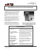
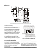
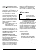
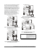

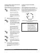
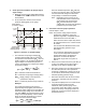
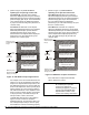
Table Of Contents

6 P—
P470 Electronic Pressure Control with Display Product/Technical Bulletin
A
djustments
This section provides instructions for setting up and
adjusting the P470 control using the internal jumpers
and front panel touchpad.
Positioning the Jumpers
The
P5
jumper-pin terminal has a single pair of jumper
pins and is used to lock or unlock the touchpad. The
P6
jumper-pin terminal has two pairs of jumper pins
and is used to establish the control’s operating
pressure range.
To position a jumper in the Installed position, place the
jumper on both pins. To position a jumper in the
Removed position, place the jumper on only one pin.
(Save the jumper in case it is required in the future.)
See Figure 8.
Jumper
Pins
(Jumper Positioned
on One Pin)
Removed
Installed
(Jumper Positioned
on Both Pins)
=
=
Figure 8: Positioning the Jumpers
Set the jumpers as follows, using Figures 8 and 9 as
guides.
1. Disconnect all power sources to the P470 control.
2. Remove the control’s cover by loosening the
four captive cover screws.
3. Position the jumpers to set the desired operating
pressure range and lock or unlock the touchpad.
4. Replace the cover, and restore power to the
control.
IMPORTANT: The P470 control’s three field-
selectable operating pressure
ranges require specific P399
transducer models for the control
to operate properly.
Do not use
a transducer model that is not
specified for the P470 control’s
field-selected operating
pressure range.
See Table 1.
P5
Touchpad
Locked
(Jumper Removed)
Touchpad
Unlocked
(Jumper Installed)
0-100 psi Range
Both Jumpers in
Removed Position
0-500 psi Range
JMP1 Installed
JMP2 Removed
50-750 psi Range
JMP1 Removed
JMP2 Installed
Unused Setting
Both Jumpers in
Installed Position
P6
(Error message
is displayed.)
Figure 9: Jumper Positions for Locking Touchpad
and Establishing the P470 Control’s Operating
Pressure Range
Table 1: Specified P399 Transducer Models, Required Jumper Positions with the
Resulting Operating Pressure Ranges, and Factory Settings at Start Up
P399
Transducer
Model
Number
Pressure
Connection
Fitting
Required
P6 Jumper
Positions
Control’s
Operating
Pressure
Range
Factory
Set
Cut-in*
(in psi)
Factory
Set
Cutout*
(in psi)
Minimum
Setpoint
Differential
Factory Set
Setpoint
Differential
P399AAA-1
1/8 in. NPT Male
P399AAC-1
1/4 in. SAE Female
(Schrader Fitting)
JMP1 Removed
JMP2 Removed
0-100 psi S1-40
S2-45
S1-20
S2-25
5 psi 20 psi
P399BAA-1
1/8 in. NPT Male
P399BAC-1
1/4 in. SAE Female
(Schrader Fitting)
JMP1 Installed
JMP2 Removed
0-500 psi S1-250
S2-220
S1-190
S2-160
20 psi 60 psi
P399CAA-1
1/8 in. NPT Male
P399CAC-1
1/4 in. SAE Female
(Schrader Fitting)
JMP1 Removed
JMP2 Installed
50-750 psi S1-250
S2-220
S1-190
S2-160
20 psi 60 psi
*S1 = Primary Setpoint Value and S2 = Secondary Setpoint Value