
Product Overview
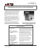
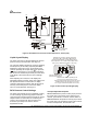
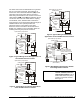

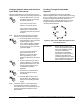
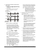
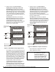
Table Of Contents

8 P—
P470 Electronic Pressure Control with Display Product/Technical Bulletin
T
roubleshooting
!
WARNING:
Risk of Electrical Shock.
To perform the following
procedures, it may be necessary
to power the control and the
controlled equipment while the
control cover is removed. Do not
touch any exposed metal
components with anything other
than properly insulated tools or
insulated probes of the digital
voltage meter. Failure to use
properly insulated tools and
probes can result in severe
electrical shock or death if live
line voltage parts are contacted.
IMPORTANT:
The P470 pressure control and
P399 transducer are not field
repairable.
Perform the following
procedures, in the order they are
presented, to determine the
problem. If the problem is with
the control or transducer, contact
a Johnson Controls/PENN sales
representative for a replacement.
Determine what the proper supply voltage is for the
control you are troubleshooting. Refer to
Figures 4, 5 and 6 for the wiring diagram and terminal
designations for the control.
See Figure 3 and Table 2 for more information about
displayed codes (error codes) that appear on the LCD.
On dual control applications, disconnect one control
and check each control as a single control application
using the procedures outlined below. See Figure 7.
Equipment Needed
•
An accurate and reliable pressure gauge
connected near the transducer.
•
A reliable and accurate Digital Voltmeter (DVM)
capable of measuring AC voltage and DC voltages
down to ± 0.1 VDC in the 0 to 10 VDC range.
IMPORTANT: The control and the controlled
equipment must be powered and
operating at a stable pressure to
perform many of the following
procedures.
1. Check for proper supply voltage to the control.
a. Before powering control and equipment, check
that all of the wiring is correct and all of the
connections are tight.
b. Apply power to the control.
c. With the DVM, check the voltage between the
control’s supply power terminals:
T1
and
T2
for the low-voltage model, and
AC COM
and
120V
or
240V
for the line voltage model.
For low-voltage controls powered by a
24 VAC Class 2 transformer
, select AC volts
on the DVM. The supply voltage must be
between 20 and 30 VAC.
For line-voltage controls
, select AC volts on
the DVM. The supply voltage must be
between 102 and 132 VAC for controls
powered at the
120V
and
COM
terminals, and
between 177 and 264 VAC for controls
powered at the
240V
and
COM
terminals.
d. If the voltage reading is within the specified
voltage range, proceed to Step 2.
e. If the DVM reading is
not
within the indicated
voltage ranges, replace the 24 VAC Class 2
transformer or check the line voltage power
source and provide for proper power to the
control.
f. Recheck for proper supply voltage.
2. Check for proper supply voltage to the
pressure transducer.
a. Select DC volts on the DVM and measure the
voltage (
VDC
S
) between
5VDC
and the
COM
terminals on the terminal block on the upper
left side of the control.
The voltage must be 5.0 VDC (± 0.2 VDC).
If the voltage is in this range, proceed to
Step 3.
b. If the voltage is out of this range, power down
the controlled equipment and disconnect it
from the control. Disconnect the transducer
from the control. With the control powered,
measure the voltage (
VDC
S
) between the
5VDC
and
COM
terminals on the terminal
block on the upper left side of the control.
The voltage must be 5.0 VDC (± 0.2 VDC).
If the voltage is in this range, replace the P399
transducer. If the voltage is out of range,
replace the P470 control.