
Product Overview
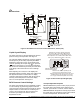
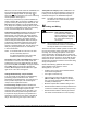

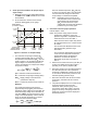
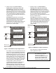
Table Of Contents

P—
P470 Electronic Pressure Control with Display Product/Technical Bulletin
9
3. Check pressure transducer for proper output
signal voltage.
a. Measure and record the voltage (
V
o
) between
the
SEN
and the
COM
terminals on the control
terminal block.
b. At the same time, observe and record the
pressure reading (
psi
T
) on the gauge.
(10%)
(90%)
(50%)
Output Voltage
(% of Power Supply)
4.5 VDC
2.5 VDC
0.5 VDC
500 psi
0-500 psi
P399B
750 psi
0-750 psi
P399C
Pressure (psi)
P470 psi Range
P399 Transducer
100 psi
0-100 psi
P399A
P
4
7
0
(
0
-
1
0
0
p
s
i
)
P
4
7
0
(
0
-
5
0
0
p
s
i
)
P
4
7
0
(
0
-
7
5
0
p
s
i
)
Figure 11: Pressure vs. Output Voltage
c. The transducer output signal voltage (
V
o
)
increases proportionally with an increase in
the pressure at the transducer (
psi
T
). Use the
graph in Figure 11 to compare the measured
signal voltage to the measured pressure or
use the formula below to compare the voltage
and pressure values.
psi =
T
10
V
o
-
o
( )
VDC
S
x
P
max
1.25 x
VDC
S
psi
T
= Pressure measured at transducer
V
o
= Transducer output signal voltage (VDC)
VDC
S
=Supply voltage to the transducer
(measured in Step 2a).
P
max
= Transducer pressure range maximum
Example:
The measured pressure at the gauge is
approximately 245 psi (
psi
T
), the measured
transducer output voltage is 2.5 VDC (
V
o
), the
measured supply voltage to the transducer is
5.03 VDC (
VDC
S
), and the transducer’s rated
range is 0 to 500 psi (
P
max
). Use the formula
above to calculate the pressure you would
expect from the measured voltage.
2.5 -
(
10
5.03
x
)
1.25 x 500
5.03
= 248.1 psi
Since the measured pressure,
psi
T
(245 psi),
is close to the pressure (248.1 psi) calculated
from the measured voltage, the transducer
output voltage is considered acceptable.
Note: Depending on the accuracy of the
instrumentation used to measure the
actual pressure at the transducer
(
psi
T
) and the transducer output
voltage (
V
o
), the actual and calculated
pressure may not exactly agree.
4. Check the control for proper operation.
Perform Steps 1-3 first.
Notes: The pressure range jumpers must be
positioned to operate the control in a
pressure range that is compatible with the
P399 transducer used. See Table 1.
When the LED is lit the output relay should
be energized and the N.O. contacts should
be closed.
Use the minimum differential value for the
selected operating pressure range.
See Table 1.
The procedures outlined below change the
cut-in and cutout setpoints and shift the
setpoint differential so the displayed
pressure is not within the Setpoint
Differential range. Refer to Figures 12
and 13.
a. Set the P470 control’s anti-short cycle delay to
0 (zero), and make sure that the control is
operating on the primary setpoints (
S1
).
b. Disconnect power to the controlled equipment
and allow the pressure in the unpowered
equipment to stabilize at a pressure of 30 psi
or more above the minimum pressure for the
selected operating pressure range.
c. Disconnect the wires from the P470 control’s
output relay, and make sure the control is
powered.
d. The pressure displayed on the control should
equal the pressure measured at the
transducer with a pressure gauge. If the
two pressure value differ greatly, check the
gauge for accuracy If the gauge checks out,
replace the control and recheck display and
measured pressure.