
Specification Sheet
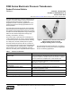
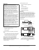
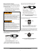
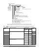
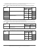
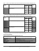
Table Of Contents

P499 Series Electronic Pressure Transducers Product/Technical Bulletin
4
Wiring in hazardous locations
P499 transducers are UL recognized for use in Class I,
Division 2 hazardous locations. Follow these additional
guidelines when wiring or servicing a P499 transducer
in a hazardous location.
• P499 Series Pressure Transducer models do not
have provisions for field wiring. They are suitable
for factory installation only. P499 transducers must
be installed in a suitable enclosure.
Figure 3 shows the wire designations for a P499
transducer used in 0.5 VDC to 4.5 VDC and 0 VDC to
10 VDC applications.
Figure 4 shows the wire designations for a P499
transducer used in 4 mA to 20 mA applications.
Figure 5 shows the wire colors for the wire terminations
in the Packard connector plug.
Figure 6 show the pins in the Packard connector socket
on the P499 transducer and the associated wire color
the pins are connected to when the Packard connector
plug is connected to the socket.
Risk of Explosion or Fire.
Do not disconnect the P499 Series Electronic Pressure
Transducer while its circuit is energized, unless the area
is known to be nonhazardous. Disconnecting the
electronic pressure transducer in a hazardous area while
its electrical circuit is energized may result in an
explosion or fire, and may cause serious injury or death.
Risque de explosion ou incendie.
Ne pas déconnecter le P499 Series Electronic Pressure
Transducer lorsque son circuit est sous tension, sauf s'il
est avéré que la zone est non dangereuse. La
déconnexion du electronic pressure transducer dans une
zone dangereuse alors que son circuit électrique est
sous tension risque d'entraîner une explosion ou un
incendie et de provoquer des blessures graves, voire
mortelles.
P499 Transducer
for 0.5 to 4.5 VDC
and 0 to 10 VDC
Applications
FIG:p499_vdc_wire s
Red Wire = Supply (+)
Black Wire = Common (-)
White Wire =
Connect cable shield lead at one point only; typically
to Common (or ground) at the control.
Output
Figure 3: Wire designations for 0.5 VDC to 4.5
VDC and 0 VDC to 10 VDC transducer applications
P499 Transducer
for 4 to 20 mA
Applications
Note:
The white wire is not used with 4 to 20 mA
transducer models. Isolate and insulate the
white wire in 4 to 20 mA transducer applications.
FIG:p499_4-20ma_wires
Red Wire = Supply (+)
Black Wire = Output (-)
White Wire = Not Used
Connect cable shield lead at one point only; typically
to Common (or ground) at the control.
Figure 4: Wire designations for 4 mA to 20 mA
transducer applications
Red Wire
Termina t ion
Black Wire
Ter mi na tio n
White Wire
Ter mi na tio n
Figure 5: Wire terminations by wire color at
Packard connector plug on wire harness
Red Wire
Ter mi na tion
Black Wire
Ter mi na tion
White Wire
Ter mi na t ion
Figure 6: Pin terminations at P499 Packard
connector socket by wire color