
Specification Sheet
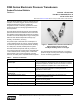
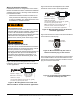
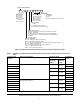
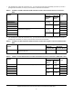
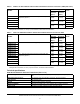
Table Of Contents

P499 Series Electronic Pressure Transducers Product/Technical Bulletin
6
4 mA to 20 mA versions
To verify that the transducer is working properly:
1. With the transducer in place and the controlled
system pressure stabilized, measure the pressure
at the transducer with an accurate and reliable
gauge. This is the measured pressure (P).
2. Determine the maximum (P
max) and minimum
(P
min) pressure values for the transducer’s
pressure range. (See Table 7.)
3. Use the equation in Figure 9 to determine the
calculated output current for the 4 mA to 20 mA
transducers.
4. Measure the P499 transducer output current. To
measure the P499 Output current: Disconnect the
P499 Output (black) wire from the control input
terminal. Set your multimeter to milliamperes (mA).
Then connect the multimeter’s red test-lead to the
P499 Output (black) wire and the multimeter’s
black test-lead to the control input terminal. The
milliamperes (mA) reading on your multimeter is
the measured output current.
5. Compare the calculated output current (Step 3) to
the measured output current (Step 4). If the current
from measured output current differs greatly from
the calculated output current, replace the
transducer.
Note: It is normal for the transducer reading to differ
somewhat from pressure gauge readings due to
multimeter and gauge tolerances, and other factors.
Repair information
Do not attempt to repair or recalibrate the P499 Series
Electronic Pressure Transducers. If a transducer does
not perform according to specifications, contact your
nearest Johnson Controls/PENN authorized distributor
or sales representative for a replacement.
Ordering
Figure 10 is a type identification matrix that identifies all
of the potential P499 Series electronic pressure
transducer types and product code numbers.
Note: Not all of the product code number
combinations (transducer types) that are possible in
Figure 10 are manufactured or available.
Contact your local Johnson Controls/PENN
representative for more information on options
available for high-volume models with specific
application requirements.
Table 3 through Table 7 provide ordering information
for standard P499 transducer models available through
most Johnson Controls/PENN authorized distributors.
See Table 2 for ordering information for wire harnesses
with Packard connectors.
I = Calculated Output Current
P = Measured Pressure
P = Maximum Pressure Value
P = Minimum Pressure Value
max
min
FIG:idl_mA
I = 4 + 16 mA
( )
P - (P )
min
Figure 9: Current calculation for 4 to 20 mA
transducers