
Install Instructions
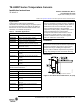
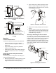
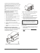


Table Of Contents

TE-6300P Series Temperature Sensors Installation Instructions2
Mounting
Location Considerations
Consider the following mounting location guidelines:
• Avoid areas subject to excessive vibration,
electrical noise, direct sunlight, or the effects of
radiant heat.
• Keep electrical wiring as short as possible to
minimize temperature error.
• Install sensors in areas where sufficient mixing of
the sensed medium occurs or use an averaging
sensor.
Cutting the Sensor Probe (Duct and Well
Models Only)
If necessary, cut the sensor probe at the wiring end
using the following procedure:
1. Mark the desired length, measuring from the end of
the tube without leads. The final sensor probe
length must be at least 3 inches (76 mm).
2. Cut the probe using a tubing cutter with a sharp
blade, as shown in Figure 4. (Cut slowly, using
minimal pressure to decrease burr size and help
avoid damaging the leads.)
3. Slide the loose tubing carefully over the leads to
remove.
4. Insert the leads into shrink tube (included) or use
other material to protect the leads from potential
sharp edges where the probe was cut. (Heat the
shrink tube using a heat gun.)
Securing or Removing the Sensor Holder
The retainer is a gray plastic tube approximately 1-1/4
in. (32 mm) long x 1/2 in. (13 mm) in diameter. Use the
retainer to lock the sensor holder into the conduit box.
Using the retainer prevents the snap finger from
deflecting, locking the sensor holder into the conduit
box. To install the retainer, slide the retainer over the
sensor wires and probe, and into the sensor holder.
(See Figure 5.)
Figure 2: Duct Averaging Sensor Dimensions,
in. (mm)
F
I
G
:
6
3
0
0
_
d
i
m
2
6.0 (152)
maximum
1/2-14 NPT Threads
Mounting Plate:
3 x 3 (76 x 76)
2.75 (69.9)
1.72
(43.7)
Figure 3: Well Insertion Sensor Dimensions,
in. (mm)
F
I
G
:
6
3
0
0
_
d
i
m
3
1/2-14 NPT Threads
Models with 6-inch
sensors have threadless
sensor holders.
7.5 (190.5) maximum (8 in.)
5.5 (139.7) maximum (6 in.)
0.52 (13)
2.75 (69.9)
6.0 (152.4)
maximum
Figure 4: Cutting the Sensor Probe
Measure
from
this end
F
I
G
:
c
u
t
_
s
n
s
Figure 5: Installing the Duct Sensor
To Controller
Sensor Holder
Retainer
F
I
G
:
i
n
s
_
s
n
s