
Install Instructions
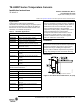
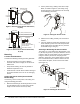
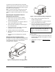


Table Of Contents

TE-6300P Series Temperature Sensors Installation Instructions 3
To remove the sensor holder from the conduit box,
slide the retainer off of the sensor probe. Push the snap
finger toward the center of the sensor holder and pull
the holder out of the conduit box.
Note: It may be necessary to loosen the set screw
and remove the sensor probe to obtain adequate
clearance to slide the sensor holder out of the conduit
box.
Mounting the Temperature Sensors
Mounting the Duct Sensor
See Figure 5 and mount the sensor as follows:
1. Drill a 1-3/8 in. (35 mm) diameter hole at the
desired mounting location.
2. Use the mounting plate as a template to drill four
1/8 in. (3 mm) holes for the screws.
3. Mount the probe assembly to the duct using the
four screws provided.
4. Pull the wires into the conduit box and snap the
conduit box onto the sensor holder.
5. Install the retainer into the sensor holder.
6. Wire the sensor to the controller using the wire nuts
provided.
7. Reposition the cover and tighten the retention
screws.
Mounting the Duct Averaging Sensor
See Figure 6 to mount a single duct averaging sensor.
See Figure 7 to mount four duct averaging sensors in
series-parallel for larger ducts. Mount the duct
averaging sensor as follows:
1. Drill a 1-3/8 in. (35 mm) diameter hole at the
desired mounting location.
2. Use the mounting plate as a template to drill four
1/8 in. (3 mm) holes for the screws.
3. Mount the averaging sensor probe inside the duct
using a TE-6001-8 or equivalent 3 in. (76 mm)
minimum radius temperature element holder.
Note: Platinum sensor models include two TE-6001-8
Element Holders.
4. Insert the sensor probe into the sensor holder and
mounting plate assembly. Firmly tighten the sensor
holder set screw.
5. Follow Steps 3 through 7 in Mounting the Duct
Sensor.
Figure 6: Installing the Duct Averaging Sensor
IMPORTANT: Do not bend the sensor probe tighter
than a 3 in. (76 mm) radius, a 6 in. (152 mm)
diameter, to avoid permanently damaging the
sensor.
Figure 7: Series-Parallel Mounting Configuration
F
I
G
:
m
n
t
_
c
n
f
g