
Install Instructions
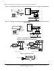
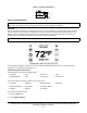
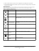
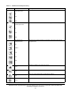
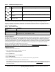
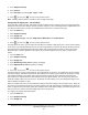
Table Of Contents
- Applications
- North American Emissions Compliance
- United States
- Canada
- Installation
- Parts Included
- Location Considerations
- Installing the Thermostat Controller
- Wiring
- Setup and Adjustments
- Overview
- Customizing the Home Screen
- Touchscreen Icons
- User Lockout
- Using the USB Port
- Loading the Firmware
- Backing Up the Settings
- Restoring the Settings
- Choosing the Communication Mode (TEC3620-00-000, TEC3621-00-000, TEC3622-00-000, and TEC3623-00-000 Models)
- Configuring the Thermostat Controller
- Installer Configuration Menu
- Screen Reset
- Selecting the Unit Type
- By default, the thermostat controller is configured for 4-pipe fan coil mode. To change to a 2-pipe or Pressure-Dependent VAV mode:
- Configuring the Supply Fan - Fan Coil Only
- Setting the Control Mode
- Setting the Fan Mode - Fan Coil Only
- Configuring the Zone Space or Equipment Size
- Changeover
- Dehumidification Control - Fan Coil Only
- Temperature Setpoints
- Configuring Occupancy
- Selecting Schedule Source
- Scheduling
- Setting the Local Schedule
- Overriding the Occupancy Mode
- Enabling Optimal Start
- Enabling the Motion Sensor (TEC3x21-00-000, TEC3x23-00-000 Models)
- PID/PRAC+ Automatic Control Tuning
- Configurable Binary Inputs
- Aux Control
- Commissioning Mode
- Sensor Priority
- Available Fault Diagnostics
- Menus and Submenus
- Troubleshooting
- Repair Information
- TEC3000 Series Proportional Fan Coil and Individual Zone Thermostat Controllers with Dehumidification Capability (Part 1 of 2)

TEC3000 Series Proportional Fan Coil and Individual Zone Thermostat Controllers with Dehumidification
Capability Installation Instructions
13
3. Enable or disable elements of the home screen as appropriate for the building owner and occupants.
4. Set the passcode on the thermostat controller to prevent the occupants from changing settings that they should
not have access to change.
Touchscreen Icons
Table 3 describes the home screen touchable icons. Press and release a touchscreen icon to activate the TEC.
Additional touchable icons appear based on the menu, and those icons are also described in Table 3.
Table 3: Touchscreen Icons (Part 1 of 3)
Icon Icon Name Description
Menu
Displays the configuration screens where various settings may be adjusted.
Alarm
Indicates that the thermostat controller has triggered an alarm.
Unit Power
On
Off
Powers the thermostat controller on or off.
Note: This icon disables all equipment control, but does not physically
power down the unit.
Network Communication
Indicates that the thermostat controller detected a supervisory controller and
both are online.
Arrow
Increases or decreases a value depending on the configuration screen.
Run/Hold
Displays the current setpoint. Hold mode is enabled by pressing the button.
No Hold/Hold
Displays the current setpoint. Hold mode is not enabled.
Hold/Hold
Displays the active setpoint. Hold mode is not enabled.
Right Arrow
Proceeds to the next screen.