
Install Instructions
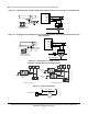
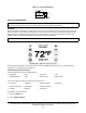
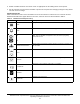
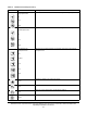
Table Of Contents
- Applications
- North American Emissions Compliance
- United States
- Canada
- Installation
- Parts Included
- Location Considerations
- Installing the Thermostat Controller
- Wiring
- Setup and Adjustments
- Overview
- Customizing the Home Screen
- Touchscreen Icons
- User Lockout
- Using the USB Port
- Loading the Firmware
- Backing Up the Settings
- Restoring the Settings
- Choosing the Communication Mode (TEC3620-00-000, TEC3621-00-000, TEC3622-00-000, and TEC3623-00-000 Models)
- Configuring the Thermostat Controller
- Installer Configuration Menu
- Screen Reset
- Selecting the Unit Type
- By default, the thermostat controller is configured for 4-pipe fan coil mode. To change to a 2-pipe or Pressure-Dependent VAV mode:
- Configuring the Supply Fan - Fan Coil Only
- Setting the Control Mode
- Setting the Fan Mode - Fan Coil Only
- Configuring the Zone Space or Equipment Size
- Changeover
- Dehumidification Control - Fan Coil Only
- Temperature Setpoints
- Configuring Occupancy
- Selecting Schedule Source
- Scheduling
- Setting the Local Schedule
- Overriding the Occupancy Mode
- Enabling Optimal Start
- Enabling the Motion Sensor (TEC3x21-00-000, TEC3x23-00-000 Models)
- PID/PRAC+ Automatic Control Tuning
- Configurable Binary Inputs
- Aux Control
- Commissioning Mode
- Sensor Priority
- Available Fault Diagnostics
- Menus and Submenus
- Troubleshooting
- Repair Information
- TEC3000 Series Proportional Fan Coil and Individual Zone Thermostat Controllers with Dehumidification Capability (Part 1 of 2)

TEC3000 Series Proportional Fan Coil and Individual Zone Thermostat Controllers with Dehumidification
Capability Installation Instructions
15
User Lockout
You can select from three different levels of access at the local display to manage functionality through the
supervisory controller. This lockout is independent of any display or passcode settings. The existing temporary
occupancy capability is unaffected by this feature. User lockout hides the icons that are not operable. The lockout
levels are described inTable 4.
Using the USB Port
The USB port allows you to quickly and easily load firmware upgrades, backup settings, and restore settings to the
TEC3000 by using a USB drive. The TEC3000 can recognize eight configuration files or firmware package files.
The USB drive format must be FAT or FAT32. The drive cannot be NTFS or USB 3.0. If you are upgrading firmware
or copying configuration files, you need the TEC3000 passcode, if it has been set up. Do not remove the USB drive
until the firmware upgrade is complete. The TEC3000 may restart and go offline to the NAE after a firmware
upgrade. The upgrade takes approximately three minutes.
Configurations are copied, except for the Communication mode. See Choosing the Communication Mode
(TEC3620-00-000, TEC3621-00-000, TEC3622-00-000, and TEC3623-00-000 Models) to configure each device.
Loading the Firmware
1. Ensure that the TEC screen is on.
2. Insert the USB drive into the right side of the TEC.
See Figure 1 for the USB port location.
3. Press the Menu icon.
4. Scroll down the menu and press Update.
5. Press Load Firmware.
6. Select the correct firmware version. The correct file name has the .pkg extension.
7. Press Confirm if you have the correct firmware version.
The firmware is loaded from the USB drive into the TEC3000 operating system. The TEC3000 locates the new
firmware only if the new firmware is on the root drive of the USB drive. See Troubleshooting
if the firmware is
not loaded correctly.
Clear
Clears the password entry on the keypad screen.
Wrench
Indicates that the value is editable.
Checkmark
Indicates that an event or schedule is programmed for a specific day of the
week.
Exclamation Point
Indicates that an error has occurred.
Table 4: User Lockout Levels
Lockout Level Capability
State 0
Allows full access to Home Screen Display Adjustments and icons (default).
State 1
Hides the Menu icon.
State 2
Only allows the screen to trigger temporary occupancy. Menu, Unit Power, the Up
and Down arrows, and Run/Hold are hidden.
Table 3: Touchscreen Icons (Part 3 of 3)
Icon Icon Name Description