
Install Instructions
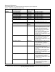

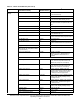

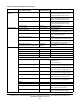
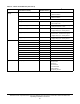
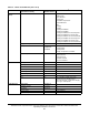
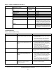
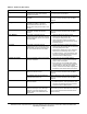
Table Of Contents
- Applications
- North American Emissions Compliance
- United States
- Canada
- Installation
- Parts Included
- Location Considerations
- Installing the Thermostat Controller
- Wiring
- Setup and Adjustments
- Overview
- Customizing the Home Screen
- Touchscreen Icons
- User Lockout
- Using the USB Port
- Loading the Firmware
- Backing Up the Settings
- Restoring the Settings
- Choosing the Communication Mode (TEC3620-00-000, TEC3621-00-000, TEC3622-00-000, and TEC3623-00-000 Models)
- Configuring the Thermostat Controller
- Installer Configuration Menu
- Screen Reset
- Selecting the Unit Type
- By default, the thermostat controller is configured for 4-pipe fan coil mode. To change to a 2-pipe or Pressure-Dependent VAV mode:
- Configuring the Supply Fan - Fan Coil Only
- Setting the Control Mode
- Setting the Fan Mode - Fan Coil Only
- Configuring the Zone Space or Equipment Size
- Changeover
- Dehumidification Control - Fan Coil Only
- Temperature Setpoints
- Configuring Occupancy
- Selecting Schedule Source
- Scheduling
- Setting the Local Schedule
- Overriding the Occupancy Mode
- Enabling Optimal Start
- Enabling the Motion Sensor (TEC3x21-00-000, TEC3x23-00-000 Models)
- PID/PRAC+ Automatic Control Tuning
- Configurable Binary Inputs
- Aux Control
- Commissioning Mode
- Sensor Priority
- Available Fault Diagnostics
- Menus and Submenus
- Troubleshooting
- Repair Information
- TEC3000 Series Proportional Fan Coil and Individual Zone Thermostat Controllers with Dehumidification Capability (Part 1 of 2)

TEC3000 Series Proportional Fan Coil and Individual Zone Thermostat Controllers with Dehumidification
Capability Installation Instructions
36
Control Setup
(Cont.)
Cool Time Constant* 720 seconds 360 to 1,440 seconds
*Values only appear when the Temp
control equals Manual PID Tuning.
Cool Process Dead Time* 72 seconds 20 to 120 seconds
*Values only appear when the Temp
control equals Manual PID Tuning.
Cool Period* 60 seconds 30 to 120 seconds
*Values only appear when the Temp
control equals Manual PID Tuning.
Equipment Size Normal Normal or Oversized
Network Setup FC Comm Mode BACnet/MSTP BACnet/MSTP, N2
BACnet Instance ID* 1 0 to 4,914,302
* BACnet/MSTP communication mode
N2 Device Address* 4 1 to 255
* N2 communication mode
BACnet Device Address* 4 4 to 127
* BACnet/MSTP communication mode
MSTP Baud Rate* Auto Auto, 1200, 9600, 19200, 38400, 76800
* BACnet/MSTP communication mode
BACnet Encoding Type
BACnet/MSTP Communication Mode
ISO 10646
(UCS-2)
ISO 10646 (UCS-2), ANSI X3.4
(US-ASCII)
Equipment Setup General
Unit Type 4-Pipe 2-Pipe, 4-Pipe, VAV
Valve Open Voltage 10 VDC 0 to 10 VDC
Valve Closed Voltage 0 VDC 0 to 10 VDC
Unoccupied Off Delay 10 minutes 0 to 10 minutes
Supply Fan
Supply Fan Type* Single-Speed Single-Speed, Multi-Speed,
Variable-Speed
*Fan coil units only
Start Voltage* 2 VDC 0 to 10 VDC
*Fan coil units only, variable speed fan
Full Speed Voltage* 10 VDC 0 to 10 VDC, proportional
*Fan coil units only, variable speed fan
Min Command* 20% 0 to 100%
*Fan coil units only, variable speed fan
Med Fan Speed On Cmd* 33% 0 to 100%
*Fan coil units only, multi-speed fan
High Fan Speed On Cmd* 66% 0 to 100%
*Fan coil units only, multi-speed fan
Reheat
Reheat Installed No Yes (True) or No (False)
Reheat Min Damper Position* 20% 0 to 100%
*VAV units with reheat installed
Reheat Fan Required* No Yes or No
*Fan coil units with reheat installed
Table 10: Menus and Submenus (Part 5 of 8)
Level 1 Level 2
(LCD Screen Name)
Level 3
(Default Values)
Available Values
1