
Install Instructions
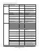
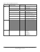
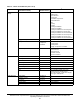
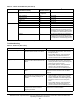
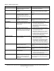
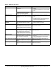
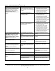
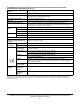
Table Of Contents
- Applications
- North American Emissions Compliance
- United States
- Canada
- Installation
- Parts Included
- Location Considerations
- Installing the Thermostat Controller
- Wiring
- Setup and Adjustments
- Overview
- Customizing the Home Screen
- Touchscreen Icons
- User Lockout
- Using the USB Port
- Loading the Firmware
- Backing Up the Settings
- Restoring the Settings
- Choosing the Communication Mode (TEC3620-00-000, TEC3621-00-000, TEC3622-00-000, and TEC3623-00-000 Models)
- Configuring the Thermostat Controller
- Installer Configuration Menu
- Screen Reset
- Selecting the Unit Type
- By default, the thermostat controller is configured for 4-pipe fan coil mode. To change to a 2-pipe or Pressure-Dependent VAV mode:
- Configuring the Supply Fan - Fan Coil Only
- Setting the Control Mode
- Setting the Fan Mode - Fan Coil Only
- Configuring the Zone Space or Equipment Size
- Changeover
- Dehumidification Control - Fan Coil Only
- Temperature Setpoints
- Configuring Occupancy
- Selecting Schedule Source
- Scheduling
- Setting the Local Schedule
- Overriding the Occupancy Mode
- Enabling Optimal Start
- Enabling the Motion Sensor (TEC3x21-00-000, TEC3x23-00-000 Models)
- PID/PRAC+ Automatic Control Tuning
- Configurable Binary Inputs
- Aux Control
- Commissioning Mode
- Sensor Priority
- Available Fault Diagnostics
- Menus and Submenus
- Troubleshooting
- Repair Information
- TEC3000 Series Proportional Fan Coil and Individual Zone Thermostat Controllers with Dehumidification Capability (Part 1 of 2)

TEC3000 Series Proportional Fan Coil and Individual Zone Thermostat Controllers with Dehumidification
Capability Installation Instructions
41
Firmware Mismatch The previous upgrade has not
completed.
1. Upgrade the TEC3000 to the latest released
version.
2. Upgrade the TEC3000 to the current version
again.
The previous downgrade has not
completed because the previous
version is no longer supported.
Reboot the TEC3000 to clear the fault.
USB Malfunction A USB drive has malfunctioned and
drawn more than the maximum allowed
current.
1. Attempt to insert and use the USB drive
again.
2. Try a new USB drive.
3. If problems persist, order replacement units
and return the affected devices to Johnson
Controls under the RMA program.
Supply Fan Runtime Limit
Extended
The Supply Fan Runtime has exceeded
the configured Supply Fan Runtime
Limit.
1. Service the Supply Fan.
2. Reset the Supply Fan runtime.
Heating Ineffective The Supply Air Temperature has not
increased above the configured Supply
Air Temperature Alarm Offset while
heating has been active for at least the
Supply Air Temperature Alarm Delay.
Verify that the heating elements on the rooftop
are functioning properly.
Cooling Ineffective The Supply Air Temperature has not
decreased below the configured Supply
Air Temperature Alarm Offset while
cooling has been active for at least the
Supply Air Temperature Alarm Delay.
Verify that the cooling elements on the rooftop are
functioning properly.
Supply Fan Fault The Supply Fan Status configured for
either BI1 or BI2 has not proved within
the configured Fan Alarm Delay.
1. Verify that the Supply Fan is operating when
turned on.
2. Verify that the Supply Fan Status wiring is
connected correctly.
Zone Temperature Too Cold The Zone Temperature has decreased
below the configured Zone Temp Low
Limit.
Verify that the TEC and the RTU heating are
enabled and functioning.
Zone Temperature Too Hot The Zone Temperature has increased
above the configured Zone Temp High
Limit.
Verify that the TEC and the RTU cooling are
enabled and functioning.
Table 11: Fault List (Part 3 of 3)
Faults Probable Causes Solutions