
Install Instructions
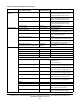
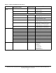
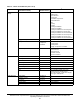
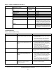
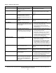
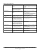
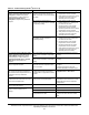
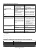
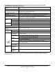
Table Of Contents
- Applications
- North American Emissions Compliance
- United States
- Canada
- Installation
- Parts Included
- Location Considerations
- Installing the Thermostat Controller
- Wiring
- Setup and Adjustments
- Overview
- Customizing the Home Screen
- Touchscreen Icons
- User Lockout
- Using the USB Port
- Loading the Firmware
- Backing Up the Settings
- Restoring the Settings
- Choosing the Communication Mode (TEC3620-00-000, TEC3621-00-000, TEC3622-00-000, and TEC3623-00-000 Models)
- Configuring the Thermostat Controller
- Installer Configuration Menu
- Screen Reset
- Selecting the Unit Type
- By default, the thermostat controller is configured for 4-pipe fan coil mode. To change to a 2-pipe or Pressure-Dependent VAV mode:
- Configuring the Supply Fan - Fan Coil Only
- Setting the Control Mode
- Setting the Fan Mode - Fan Coil Only
- Configuring the Zone Space or Equipment Size
- Changeover
- Dehumidification Control - Fan Coil Only
- Temperature Setpoints
- Configuring Occupancy
- Selecting Schedule Source
- Scheduling
- Setting the Local Schedule
- Overriding the Occupancy Mode
- Enabling Optimal Start
- Enabling the Motion Sensor (TEC3x21-00-000, TEC3x23-00-000 Models)
- PID/PRAC+ Automatic Control Tuning
- Configurable Binary Inputs
- Aux Control
- Commissioning Mode
- Sensor Priority
- Available Fault Diagnostics
- Menus and Submenus
- Troubleshooting
- Repair Information
- TEC3000 Series Proportional Fan Coil and Individual Zone Thermostat Controllers with Dehumidification Capability (Part 1 of 2)

TEC3000 Series Proportional Fan Coil and Individual Zone Thermostat Controllers with Dehumidification
Capability Installation Instructions
43
Repair Information
If the TEC3000 Series Thermostat Controller fails to operate within its specifications, replace the unit. For a
replacement thermostat controller, contact the nearest Johnson Controls representative.
Technical Specifications
The controller is unable to access a
USB drive.
The drive is formatted as NTFS or
another unsupported format. The TEC
supports FAT and FAT32 formats only.
Reformat the USB drive, or try a
different USB drive with a supported
format.
The USB drive is defective. Try a different USB drive.
The controller displays Board
Mismatch.
The I/O board that the display board is
currently attached to does not match
the one that initially shipped with the
display board.
Attach the display board to the correct
I/O board.
A hardware failure is causing the two
boards to incorrectly identify
themselves.
Order replacement units and return the
affected devices to Johnson Controls
under the RMA program.
The controller displays Controller
Fault.
An internal fault was detected and the
controller was unable to recover.
Order replacement units and return the
affected devices to Johnson Controls
under the RMA program.
The Bell icon is displayed on the TEC
home page.
The fault has been detected on the
TEC.
See Table 11 for TEC fault causes and
resolution.
Partial Restore Complete is displayed
when trying to restore settings from a
backup file.
Not all of the items in the backup file
have been restored. This error can be
caused by a value being out of the
minimum or maximum range in the
backup file. It may also occur if there
are inconsistencies in the reliability of a
setting in the backup file and on the
TEC device.
1. Create a Backup file on a USB
drive for the TEC that is showing
the issue.
2. Edit the backup file created in the
previous step on a PC to reflect the
desired settings.
3. Verify that the modified values are
within minimum and maximum
range in the backup file.
4. Restore the settings from the newly
edited backup file on the TEC.
The temperature displayed is lower
than the actual room temperature.
Cold air drafts are entering the back of
the TEC.
Seal any holes behind the TEC to
reduce drafts.
Air is being forced through the TEC
from a nearby vent.
Move the location of the TEC or
change the venting to prevent air from
being forced through the TEC.
The Online icon does not appear for a
networked controller.
There is improper field bus wiring. Refer to the MS/TP Communications
Bus Technical Bulletin (LIT-12011034).
Some icons are hidden. Lockout levels are used or the icons
are hidden due to the display settings.
See Table 4 for lockout levels and
access details.
1. For common MS/TP troubleshooting information, refer to the MS/TP Communications Bus Technical Bulletin
(LIT-12011034).
TEC3000 Series Proportional Fan Coil and Individual Zone Thermostat Controllers with
Dehumidification Capability (Part 1 of 2 )
Power Requirements 19 to 30 VAC, 50/60 Hz, 4 VA at 24 VAC nominal, Class 2 or
safety extra-low voltage (SELV)
USB Port Power Rating 120 to 250 mA current draw supported
Analog Output Rating 0 to 10 VDC into 2k ohm resistance (minimum)
Fan Relay Output Rating 19 to 30 VAC, 1.0 A maximum, 15 mA minimum, 3.0 A in-rush
Table 12: Troubleshooting Details
1
(Part 2 of 2)
Symptom Probable Causes Solutions