
Install Instructions
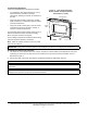
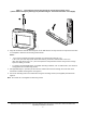
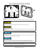
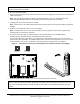
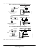
Table Of Contents
- Applications
- North American Emissions Compliance
- United States
- Canada
- Installation
- Parts Included
- Location Considerations
- Installing the Thermostat Controller
- Wiring
- Setup and Adjustments
- Overview
- Customizing the Home Screen
- Touchscreen Icons
- User Lockout
- Using the USB Port
- Loading the Firmware
- Backing Up the Settings
- Restoring the Settings
- Choosing the Communication Mode (TEC3620-00-000, TEC3621-00-000, TEC3622-00-000, and TEC3623-00-000 Models)
- Configuring the Thermostat Controller
- Installer Configuration Menu
- Screen Reset
- Selecting the Unit Type
- By default, the thermostat controller is configured for 4-pipe fan coil mode. To change to a 2-pipe or Pressure-Dependent VAV mode:
- Configuring the Supply Fan - Fan Coil Only
- Setting the Control Mode
- Setting the Fan Mode - Fan Coil Only
- Configuring the Zone Space or Equipment Size
- Changeover
- Dehumidification Control - Fan Coil Only
- Temperature Setpoints
- Configuring Occupancy
- Selecting Schedule Source
- Scheduling
- Setting the Local Schedule
- Overriding the Occupancy Mode
- Enabling Optimal Start
- Enabling the Motion Sensor (TEC3x21-00-000, TEC3x23-00-000 Models)
- PID/PRAC+ Automatic Control Tuning
- Configurable Binary Inputs
- Aux Control
- Commissioning Mode
- Sensor Priority
- Available Fault Diagnostics
- Menus and Submenus
- Troubleshooting
- Repair Information
- TEC3000 Series Proportional Fan Coil and Individual Zone Thermostat Controllers with Dehumidification Capability (Part 1 of 2)

TEC3000 Series Proportional Fan Coil and Individual Zone Thermostat Controllers with Dehumidification
Capability Installation Instructions
6
To wire the thermostat controller:
1. Strip the ends of each wire 1/4 in. (6 mm) and connect them to the appropriate screw terminals as indicated in
Table 2 and Figure 7.
Note: For more details on wiring the MS/TP Communications Bus, refer to the TEC3000 Series and
Field-Selectable BACnet® MS/TP or N2 Networked Thermostat Controllers (LIT-12011956).
2. Carefully push any excess wire back into the wall.
Note: Seal the hole in the wall with fireproof material to prevent drafts from affecting the ambient temperature
readings.
3. Reattach the communication wires to the terminal block.
Note: If multiple wires are inserted into the terminals, be sure to properly twist the wires together before
inserting them into the terminal connectors.
4. Set the bus end-of-line (EOL) termination switch to the desired location on the TEC3620-00-000,
TEC3621-00-000, TEC3622-00-000, and TEC3623-00-000 models only.
The bus EOL termination switch allows you to designate the thermostat controller as the end of the Field
Controller (FC) Bus and N2 Bus. The default position is OFF. If the thermostat controller is at the end of a daisy
chain of devices on the FC Bus and N2 Bus, set the EOL switch to the ON position. See Figure 4.
Figure 4: EOL Switch Position (Left) and Installing the Thermostat Controller Cover (Right)
5. Reattach the thermostat controller cover to the mounting base (bottom side first).
IMPORTANT: Use proper ESD precautions during installation and servicing to avoid damage to the electronic
circuits of the thermostat controller.
IMPORTANT: Make sure you reattach the cover that corresponds to its correct base. The CPU board number
needs to match the base board number.
Otherwise, an operation error occurs after you reattach a cover and
base that do not belong together (as shown in Figure 5). See Table 1 for TEC3000 model names and code
numbers.
FIG:EOL_Swtch
EOL Switch
ON Position
EOL Switch
OFF Position
O
N
O
N
FIG:TEC Backplane2_EOL Switch
O
N
FIG:close thermostat cover