
Install Instructions
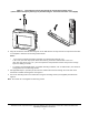
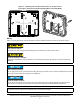
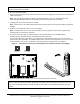
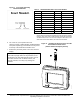
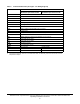
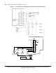
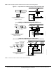
Table Of Contents
- Applications
- North American Emissions Compliance
- United States
- Canada
- Installation
- Parts Included
- Location Considerations
- Installing the Thermostat Controller
- Wiring
- Setup and Adjustments
- Overview
- Customizing the Home Screen
- Touchscreen Icons
- User Lockout
- Using the USB Port
- Loading the Firmware
- Backing Up the Settings
- Restoring the Settings
- Choosing the Communication Mode (TEC3620-00-000, TEC3621-00-000, TEC3622-00-000, and TEC3623-00-000 Models)
- Configuring the Thermostat Controller
- Installer Configuration Menu
- Screen Reset
- Selecting the Unit Type
- By default, the thermostat controller is configured for 4-pipe fan coil mode. To change to a 2-pipe or Pressure-Dependent VAV mode:
- Configuring the Supply Fan - Fan Coil Only
- Setting the Control Mode
- Setting the Fan Mode - Fan Coil Only
- Configuring the Zone Space or Equipment Size
- Changeover
- Dehumidification Control - Fan Coil Only
- Temperature Setpoints
- Configuring Occupancy
- Selecting Schedule Source
- Scheduling
- Setting the Local Schedule
- Overriding the Occupancy Mode
- Enabling Optimal Start
- Enabling the Motion Sensor (TEC3x21-00-000, TEC3x23-00-000 Models)
- PID/PRAC+ Automatic Control Tuning
- Configurable Binary Inputs
- Aux Control
- Commissioning Mode
- Sensor Priority
- Available Fault Diagnostics
- Menus and Submenus
- Troubleshooting
- Repair Information
- TEC3000 Series Proportional Fan Coil and Individual Zone Thermostat Controllers with Dehumidification Capability (Part 1 of 2)

TEC3000 Series Proportional Fan Coil and Individual Zone Thermostat Controllers with Dehumidification
Capability Installation Instructions
8
Table 2: Terminal Identification (See Figure 7 for Wiring Diagram)
Terminal Label Function
TEC3320, TEC3321, TEC3322,
TEC3323, Proportional FC/VAV
TEC3620, TEC3621, TEC3622,
TEC3623 Proportional FC/VAV
24 V 24 VAC hot from transformer
FAN H Fan high
FAN M Fan medium
FAN L Fan low and fan on
AUX Auxiliary binary output
AUX Auxiliary power
COM
1
24 VAC common from transformer
CLG Cooling command (configurable 0 to 10 V range)
NC No connection
HTG Heating command (configurable 0 to 10 V range)
COM
1
Common
VSF Variable speed fan command (configurable 0 to 10 V range)
BI2 Configurable binary input 2
BI1 Configurable binary input 1
COS Changeover sensor
R SEN Zone temperature sensor
NET+ Not connected Field bus+/N2+
NET- Not connected Field bus-/N2-
NET COM Not connected Isolated common for field bus
1. The common terminals, which do not include NET COM, are internally connected and can be used for
all inputs and outputs.