
Install Instructions
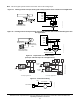
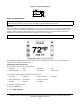
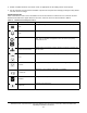
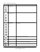
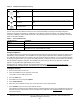
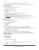
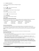
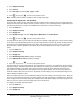
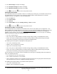
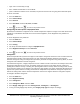
Table Of Contents
- Applications
- North American Emissions Compliance
- United States
- Canada
- Installation
- Parts Included
- Location Considerations
- Installing the Thermostat Controller
- Wiring
- Setup and Adjustments
- Overview
- Customizing the Home Screen
- Touchscreen Icons
- User Lockout
- Using the USB Port
- Loading the Firmware
- Backing Up the Settings
- Restoring the Settings
- Choosing the Communication Mode (TEC3620-00-000, TEC3621-00-000, TEC3622-00-000, and TEC3623-00-000 Models)
- Configuring the Thermostat Controller
- Installer Configuration Menu
- Screen Reset
- Selecting the Unit Type
- By default, the thermostat controller is configured for 4-pipe fan coil mode. To change to a 2-pipe or Pressure-Dependent VAV mode:
- Configuring the Supply Fan - Fan Coil Only
- Setting the Control Mode
- Setting the Fan Mode - Fan Coil Only
- Configuring the Zone Space or Equipment Size
- Changeover
- Dehumidification Control - Fan Coil Only
- Temperature Setpoints
- Configuring Occupancy
- Selecting Schedule Source
- Scheduling
- Setting the Local Schedule
- Overriding the Occupancy Mode
- Enabling Optimal Start
- Enabling the Motion Sensor (TEC3x21-00-000, TEC3x23-00-000 Models)
- PID/PRAC+ Automatic Control Tuning
- Configurable Binary Inputs
- Aux Control
- Commissioning Mode
- Sensor Priority
- Available Fault Diagnostics
- Menus and Submenus
- Troubleshooting
- Repair Information
- TEC3000 Series Proportional Fan Coil and Individual Zone Thermostat Controllers with Dehumidification Capability (Part 1 of 2)

TEC3000 Series Proportional Fan Coil and Individual Zone Thermostat Controllers with Dehumidification
Capability Installation Instructions
11
Note: VAV and 2-pipe systems should connect their valve to the heating output.
Figure 11: Floating Control Two-Pipe Heating and Cooling Hydronic Valve Control Fan Coil Application
Figure 12: Floating Control Two-Pipe Heating and Cooling Hydronic Valve Control with Changeover Fan
Coil Application
Figure 13: Proportional 0 to 10 VDC Control
(Two-Pipe and Four-Pipe Fan Coil Applications)
Figure 14: AUX Contact Wiring
FIG:model_2_htng_clng_hdrnc
Room Temperature
Control Thermostat
0 to 10
VDC
COS
COM
24V
HTG
FIG:model_2_htng_clng_hdrnc_chngvr
Proportional
Heating/Cooling
Valve
Optional Water
Supply Sensor
Room Temperature
Control Thermostat
Supply Water
Temperature Sensor
0 to 10
VDC
COS
COM
24V
HTG
Two-Pipe Applications
Four-Pipe Applications
FIG:model_2_proportional
Heating/Cooling
Valve
COM
24V
CLG
HTG
Cooling
Valve
Heating
Valve
COM
24V
HTG
AUX Contact
FIG:Aux Contact Wiring
Load
Hot
19 to 30 VAC