
User Guide
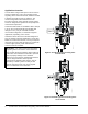

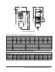
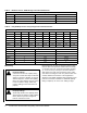
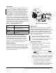
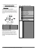
Table Of Contents

V46 Pressure-Actuated Water-Regulating Valve Product Bulletin10
3. Companion flange kit by part number, if required.
See Companion Flanges and Gaskets
.
4. Mounting bracket (3/8 in. and 1/2 in. valve sizes
only) if required, and its position on valve. See
Mounting Bracket
.
Companion Flanges and Gaskets
Kits are available, at additional cost, for 1-1/2, 2, and
2-1/2 in. flange connection (ASME specifications)
valves only. Each flange kit contains two ring gaskets,
two cast iron flanges, eight machine bolts, and eight
hex nuts.
Product Number Selection
For applications that call for valves not listed in
Table 10 through Table 14, Table 8 can be used to
specify a custom valve. For example, to order a
direct-acting, commercial valve with a 1-1/4 in. NPT
threaded connection, specify a V46AE. For more
information, contact Application Engineering at (414)
274-5535.
Table 7: Companion Flange Kits
Kit Number Water Valve Size
KIT 14A-612 1-1/2 in.
KIT 14A-613 2 in.
KIT 14A-614 2-1/2 in.
Figure 20: Flange Kit
Cast Iron
Ring Gasket for
FIG:flng_kt
Table 8: Type Number Selection Matrix
V46 A Open on Rise, Commercial
B Open on Rise, Maritime
C Open on Rise, Navy
D Open on Rise, Commercial Low Flow
E Open on Rise, Commercial with
High Pressure Bellows
F Open on Rise, Maritime with
High Pressure Bellows
G Open on Rise, Navy with
High Pressure Bellows
L Open on Rise, Commercial Low Flow
No-Repair
N Open on Fall, Commercial
P Open on Fall, Maritime
Q Open on Fall, Commercial Low Flow with
High Pressure Bellows
A 3/8 in. NPT Threaded
B 1/2 in. NPT Threaded
C 3/4 in. NPT Threaded
D 1 in. NPT Threaded
E 1-1/4 in. NPT Threaded
F 1-1/2 in. NPT Threaded
G 9/16–18 Threaded
H 3/8 in. Sweat
J 1/2 in. Sweat
K 3/4 in. Sweat
L 1 in. Sweat
M 1-1/4 in. Sweat
N 3/4 in. Flange
P 1 in. Flange
Q 1-1/4 in. Flange
R 1-1/2 in. Flange
S 2 in. Flange
T 2-1/2 in. Flange