
User Guide
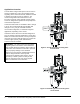
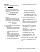
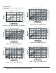
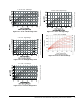

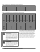
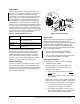
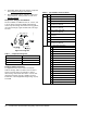
Table Of Contents

V46 Pressure-Actuated Water-Regulating Valve Product Bulletin 3
Valve Sizing
Follow Steps 1 through 3, and use the information
obtained to locate a point on one of the flowcharts
found under V46 Flowcharts
that satisfies all three
steps.
1. Determine maximum water flow required using
tables provided by the manufacturer of the
condensing unit, or calculate the flow using the
following formula:
Note: If the outlet water temperature is unknown,
assume it to be 10°F below the condensing
temperature.
Example: A 9-ton capacity system has an inlet
water temperature of 65°F and an outlet water
temperature of 95°F. The maximum required water
flow is:
2. Determine refrigerant head pressure rise above the
valve opening point.
a. Valve closing point (to assure closure under all
conditions) must be the refrigerant pressure
equivalent to the highest ambient air
temperature the equipment will be subjected to
in the off cycle. Read this in psig from a
Saturated Vapor Table for the refrigerant
selected.
b. To determine the valve opening point, add
about 7 psig (48 kPa) to the closing point.
c. From the same table, read the operating head
pressure corresponding to the selected
condensing temperature.
d. Subtract the valve opening point from the
operating head pressure. This gives the head
pressure rise.
3. Determine water pressure drop across the valve.
This is the pressure actually available to force
water through the valve.
a. Determine minimum water pressure available
from city mains or other sources.
b. From condensing unit manufacturer’s tables,
read the pressure drop through condenser
corresponding to the required flow.
c. To the value found in 3b, add the estimated or
calculated drop through installed piping.
d. Subtract the total condenser, piping, and static
head (if applicable) pressure drop from the
available water pressure found in 3a. This is
the available pressure drop across the valve.
4. Select the proper valve size from the V46
flowcharts by locating a point on a chart that will
satisfy the flow, the head pressure rise above
opening point, and the pressure drop across the
valve.
Example: The required flow for a low-range system
is found to be 27 GPM. Condensing pressure is
125 psig, and the maximum ambient temperature
is estimated at 86°F. City water pressure is 40 psig
and the manufacturer’s table gives a pressure drop
through the condenser and the accompanying
piping and valves at 15 psi. Drop through the
installed piping is approximately 4 psi.
Step 1: 27 GPM
Step 2: Closing point is pressure of refrigerant
corresponding to 86°F = 93 psig
Opening point = 93+7 = 100 psig
Operating head pressure = 125 psig
Head pressure rise = 125-100 = 25 psi
Step 3: Minimum pressure = 40 psig
Pressure drop through condenser = 15 psi
Combined pressure drop = 15+4 = 19 psi
Pressure drop across valve = 40-19 = 21 psi
Using a flow of 27 GPM, a head pressure rise of 25 psi,
and a pressure drop across the valve of 21 psi, the only
valve that satisfies all three criteria is a 1-1/4 in. valve.
See the 1-1/4 in. V46 - All Range chart on the next
page.
Figure 4: Flow Equation
Figure 5: Example