
User Guide
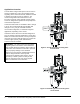
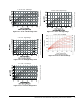

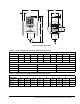
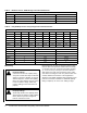
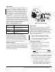
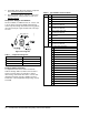
Table Of Contents

V46 Pressure-Actuated Water-Regulating Valve Product Bulletin 9
Adjustment
Valves may be adjusted with standard service valve
wrenches or screwdrivers; see Table 6. All range valve
settings can be changed quickly from low-range
refrigerants, such as R134, to high-range refrigerants,
such as R22, or from high range refrigerants to low-
range refrigerants. To raise the valve opening point,
turn the adjusting screw, located at the top of range
spring housing, counterclockwise. See Table 6 and
Figure 19. Turn the adjusting screw clockwise to lower
the opening point. Exact settings can be made using a
pressure gauge in the refrigerant line to determine the
throttling point. Put the system under normal operating
load and adjust to the desired operating pressure. See
Table 15 for pressure range specifications.
If the compressor operates in high ambient
temperatures, head pressures may remain high
enough during off cycles to prevent the valve from
closing completely. In such instances, the opening
point of the valve should be raised just enough to
cause the valve to close during compressor standby
periods. This will also raise the throttling point.
Manual Flushing
To clear any sediment that might accumulate, valves
may be manually flushed. Insert screwdrivers under
both sides of the valve spring guide and lift upwards to
flush the valve. See Figure 19. Manual flushing does
not affect valve adjustment.
Repair Data
Replacement of the sensing element, internal parts,
and the rubber diaphragm can be made. For a
replacement valve or replacement parts kit, contact the
nearest Johnson Controls/PENN® distributor. For
replacement part kit numbers, see Table 9 through
Table 14. For replacement kit instructions and details
refer to the following bulletins:
• V46, V47, V48, and V49 Sensing Element
Replacement Technical Bulletin, LIT-121700
• V46, V47, 246, and 247 Repair Parts and Service
Instructions Repair Bulletin, LIT-121695
Ordering Information
When ordering water valves, specify the following:
1. Complete product number.
2. If product number is not known, answer the
following questions and select a valve using
Table 10 through Table 14.
a. What is the valve size needed? See Valve
Sizing section.
b. What refrigerant will be used in the system?
See Table 15.
Note: 3/8 in. through 1-1/2 in. valves are supplied
with all range construction, allowing a single valve
to be used for either low or high range refrigerants.
c. Is a standard open high, or reverse action
close high valve required? See Table 8.
d. Is a commercial, maritime, or Navy service
valve needed? Maritime and Navy valves have
bronze bodies and monel internal parts.
Table 6: Range Adjustment Screw
Valve Size
(in.)
Range Adjusting Screw
3/8, 1/2, 3/4 1/4 in. square head adjusting screw
with a screwdriver slot
1, 1-1/4, 1-1/2 5/16 in. square head adjusting screw
2, 2-1/2 1/2 in. square head adjusting screw and
a slotted cam
Figure 19: Manual Flushing
FIG:V46_mnl_flsh