
Product Overview


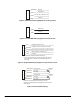

Table Of Contents

VA-4233 Series Electric Valve Actuators Product Bulletin 5
Allow a minimum
1-1/2 in. (38 mm)
top and side clearance
for actuator removal.
6-11/32
(161)
Top of
Valve Bonnet to
Top of Actuator
Face View Side View
11/32
(9)
Set Screw
4-3/32
(104)*
3-5/32
(80)
3-19/32
(91)
* Add 1-17/32 in. (39 mm)
for conduit adaptor on models
with auxiliary switches.
Stem Nut
Connector
Area
Auxiliary Switch 2
Adjustment
Auxiliary Switch 1
Adjustment
Access Door to
Actuator Settings
(Proportional Models Only)
6-13/16
(173)
Manual
Override
Socket
Figure 5: Actuator Dimensions, in. (mm)
Table 3: Repair Parts
Code Number Description
VA-4233-600 Manual Hand Crank (Includes Five Manual Hand Cranks)
VA-4233-601*
Hardware Kit (Includes One Manual Hand Crank, One
Special Stem Nut, One Jam Nut, and One Yoke Screw)
*
Items included in the hardware kit are also included with each actuator.