
Product Overview


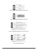

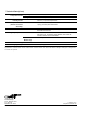
Table Of Contents

6 VA-4233 Series Electric Valve Actuators Product Bulletin
White/Brown
Brown
Yell ow
White
Common
Stem Up
Stem Down
20 to 30 VAC or 24 VDC ± 10%
Figure 6: VA-4233-AGx Wiring Diagram for Floating Control
Yell ow
White
Common
Stem Down
Figure 7: VA-4233-BGx Wiring Diagram for On/Off Control
Gray
White/Red
Yell ow
White
Red
Output 20 VDC at 25 mA*
Feedback 0 (2) to 10 VDC or 6 to 9 VDC
Input 0 (2) to 10 VDC, 6 to 9 VDC, or 0 (4) to 20 mA**
20 to 30 VAC or 24 VDC ± 10%
Common
** The control inputs shown will move the valve stem down as
the control input increases, with the DA/RA switch in the
DA mode.
* Available on VA-4233-GGx-2MP models only.
Figure 8: VA-4233-GGx Wiring Diagram for Proportional Control
White/Yellow
Black/Yellow
Switch S1
21%*
White/Gray
White/Blue
Switch S2
84%*
Black/Gray
Black/Blue
* Refers to a full actuator stroke of 29/32 in. (23 mm).
Switches are readjustable to all applicable Johnson Controls
stroke ranges.
N.C. (26)
Common (24)
N.O. (25)
Common (21)
N.O. (23)
N.C. (22)
Figure 9: Auxiliary Switch Wiring