
User Guide
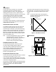
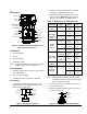
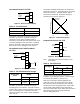
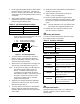
Table Of Contents

2 VA-715x Electric Valve Actuator Product/Technical Bulletin
O
peration
The VA-715x Series actuators use a reversible
synchronous motor and a magnetic clutch to
accurately position the valve. This combination can
reliably generate 90 lb of force in either direction.
The actuator maintains the shutoff force even if power
to the actuator is removed. When the controller
provides a signal for the actuator to move in the
opposite direction, the shutoff force is reduced and the
valve modulates.
The magnetic clutch maintains a constant load at the
end of travel, which ensures tight valve shutoff and
compensates for seat wear.
Incremental Control--VA-7150
A controller provides 24 VAC to the Up, Down, and
Common terminals depending upon the desired
movement of the valve stem. This signal causes the
motor to rotate in the proper direction. The gear train
and drive screw move the valve stem up or down.
When the controller stops sending a signal, the valve
stem is held in place and remains in position until the
next control signal is sent.
Note: In incremental applications, there is no direct
correlation between valve position and
controller output (0 to 100%). If correlation is
important, use proportional control or
actuators that provide position feedback.
Feedback Control--VA-7153
VA-7153 actuator operation is the same as the
VA-7150, while providing position feedback.
A 2k ohm position feedback potentiometer provides
remote position indication to the control system.
The 0 to 2k ohm feedback potentiometer is
proportional to the full 3/4 in. actuator stroke and
includes a field adjustable zero.
Proportional Control--VA-7152
The VA-7152 provides a proportional stroke in relation
to the input control signal of 0 to 10, 0 to 5,
or 5 to 10 VDC jumper selectable input control signal.
It also features stroke selection and Direct Acting (DA)
or Reverse Acting (RA) jumpers.
An electronic controller provides the proportional input
signal to the VA-7152. This signal is compared to the
actual valve position via the internal feedback
potentiometer.
The internal circuit activates the motor to rotate in the
proper direction. The gear train and drive screw move
the valve stem to the position called for by the input
signal.
Note: The actuator will accept control signals of
20 VDC maximum with signals over 10 VDC
ignored by the actuator.
Stem
Up
Reverse
Acting (RA) Mode
Direct Acting (DA)
Mode
Stem
Down
10 VDC
Signal
Increase
0 VDC
Figure 2: Direct/Reverse Action
D
imensions
0.25 in.
(6.4 mm)
Diameter
Maximum
Cable
2.50
63.5
Cover Removal
3.84
98 diameter
6.06
154
Bushing
(Pg 9)
Conduit
Threads
Figure 3: VA-715x Series Dimensions (in./mm)