
User Guide
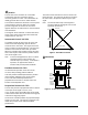
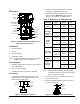
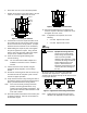
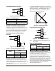
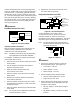
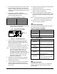
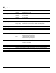
Table Of Contents

VA-715x Electric Valve Actuator Product/Technical Bulletin 3
I
nstallation
Dimension "
A"
(See Table 1
for dimensions.)
Coupler
Actuator Yoke
Jam Nut
Valve Stem
Position
Scale
Set Screw
Drive Screw
Gear
Valve
Bonnet
Position
Indicator
24 VAC
Motor
Figure 4: Actuator Components as Mounted on
VBC Series Cage Trim Valve
Kit Includes
• VA-715x Actuator
• jam nut
• position indicator
• two position scales
Note: No additional parts are required for mounting
to VBC Series valves. (See Figure 4.)
Tools Required
• wrenches, 3/4 (19 mm) and 9/16 in. (14 mm) open
end or adjustable
• nut driver, 5/16 in. (8 mm)
• screwdrivers, 3/32 in. and 3/16 in. flat-blade
Procedures
1. Verify the valve stroke by measuring the valve
stem in the full down and full up positions. The
difference is the valve stroke.
Valve Stem
Full Up
Valve Stem
Full Down
Valve Stroke
Figure 5: Measuring Valve Stroke
2. Unpack the actuator and remove its cover by
removing the single screw in the top.
3. Manually turn the gearing between the metal
plates to achieve Dimension “A” as shown in
Figure 4. (Use Table 1 to set Dimension A.)
Table 1: Dimension “A” Gap Reference
Valve Family
Valve Size or
Style
Valve
Stroke
Dimension
“A”
VT Series
Valves
1/2 in.
5/16 in.
(8 mm)
5/32 in.
(4 mm)
3/4 in.
1/2 in.
(13 mm)
5/64 in.
(2 mm)
VBC Series
Cage Trim
Valves
1, 1-1/4,
1-1/2,
and 2 in.
3/4 in.
(19 mm)
5/64 in.
(2 mm)
1/2 and 3/4 in.
5/16 in.
(8 mm)
5/64 in.
(2 mm)
VG7000
Series
1 and 1-1/4 in. 1/2 in.
(13 mm)
5/64 in.
(2 mm)
Valves
1-1/2 and 2 in. 3/4 in.
(19 mm)
5/64 in.
(2 mm)
VB-4332
(3-Way Mixing)
5/16 in.
(8 mm)
5/32 in.
(4 mm)
Flare Valves
(1/2 in. only)
VB-3766 (N.O.)
and
VB-3966 (N.C.)
1/2 in.
(13 mm)
5/64 in.
(2 mm)
Honeywell*
V50xxx
1/2 - 3 in.
3/4 in.
(19 mm)
5/64 in.
(2 mm)
Siebe*
(Barber-
Colman)
1/2 to 1-1/4 in.
3/8 in.
(9.5 mm)
5/64 in.
(2 mm)
VB-9xxx
1/2 in.
(13 mm)
5/64 in.
(2 mm)
* Requires a mounting kit from the Accessories table.
Note: It is necessary to manually turn the gearing
several times before you see movement of the
drive screw and the coupler.
4. Thread the jam nut onto the valve stem down to
the end of the thread.
5. Place the position indicator on top of the jam nut
as shown in Figure 6.
Position
Indicator
Jam Nut
Valve Stem
Figure 6: Installing Nut and Position Indicator