
User Guide
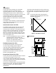
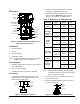
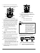
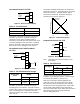
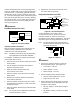
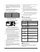
Table Of Contents

4 VA-715x Electric Valve Actuator Product/Technical Bulletin
6. Push valve stem in so it is in full down position.
7. Position the actuator on the valve bonnet, and use
a 5/16 in. nut driver to tighten the set screw.
Coupler
Valve
Stem
Set
Screw
Position
Indicator
Actuator
Yoke
Valve
Bonnet
Figure 7: Installing the Actuator
8. Lift the stem to meet the coupler and then screw
the coupler onto the stem until the valve reaches
the end of stroke in the full up position. (Coupler
should be turned a minimum of four revolutions.)
9. While holding the coupler in place, hand tighten
the jam nut against the coupler. Using 3/4 and
9/16 in. open end wrenches, tighten the coupler
and jam nut an additional 1/8 to 1/4 turn.
10. Insert the wires through the bushing in the
actuator housing.
Note: The VA-7150-1900 Conduit Adaptor Kit is
available if connection to 1/2 in. conduit is
needed.
11. Connect the wires to the actuator using the
appropriate wiring diagrams, see the Wiring
section.
12. Provide the control signal to drive the actuator up
and down at least two complete cycles to check
actuator for proper operation.
13. Verify that the actuator is fully seating the valve in
the full down position and that the initial clearance
(Step 3) is maintained in the full up position.
Note: If the valve is not fully seating in the down
position, decrease gap Dimension “A” by
reducing the thread coupler engagement. The
gap must be sufficient to allow actuator to stall
at the end of stroke.
14. Attach the position scale label to the actuator yoke
as shown in Figure 8. Place the second label on
the backside of yoke.
Position
Scale
Figure 8: Installing the Position Scale
15. Proceed with adjustments in the Adjustments
section if required. Otherwise, replace the cover
and tighten the cover screw.
Note: If adjustments are required, refer to the
following:
• VA-7152: Adjustments section
• VA-7153: Adjustments section
W
iring
!
WARNING: Equipment Damage Hazard.
Disconnect the power supply
before wiring connections are
made to prevent possible
damage to the equipment. Make
and check all wiring connections
before applying power to the
system. Short-circuited or
improperly connected wires may
result in permanent damage to
the unit.
All wiring must be in accordance with applicable
electrical code requirements. Input lines to the
actuator must be wired correctly for the valve to move
in the proper direction.
1
2 3
1 2 3
R W S
1
2 3
4
IN
COM
COM
AC
UP
UP
DWN
COM
COM
DWN
VA-7150 VA-7153 VA-7152
Figure 9: Application and Drawing Identification
Note: Follow wiring and termination instructions
detailed in the applicable controller manual.