
User Guide
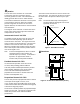
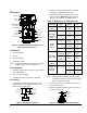
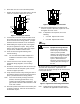
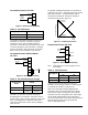
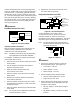
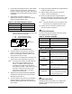
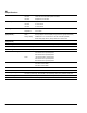
Table Of Contents

VA-715x Electric Valve Actuator Product/Technical Bulletin 5
Incremental Control--VA-7150
1
2
3
Common
Down
Up
F
r
o
m
2
4
V
AC
S
u
p
p
l
y
Figure 10: Basic Incremental Wiring
Table 2: VA-7150 Action
Energizing Terminals
Actuator Drive Screw
1-2
Extends
1-3
Retracts
Incremental control wiring should be connected to
terminals: (1) Common, (2) Down, and (3) Up.
(Terminal 17 is not used.) Providing power to
Terminals 1 and 2 will cause the actuator drive screw
to extend, pushing the valve stem down. Providing
power to Terminals 1 and 3 will cause the actuator
drive screw to retract, pulling the valve stem up.
Incremental Control with Feedback--
VA-7153
2k ohms
D
own
Fro
m
24 VAC
Supply
S
W
R
1
2
3
Common
Down
Up
Figure 11: Basic Feedback Wiring
Table 3: VA-7153 Resistance Change
Actuator Drive
Screw
Feedback Resistance
Change
R - W
W - S
Extends
Decrease Increase
Retracts
Increase Decrease
Incremental control wiring should be connected to
terminals: (1) Common, (2) Down, and (3) Up.
Providing power to Terminals 1 and 2 will cause the
actuator drive screw to extend, pushing the valve stem
down. Providing power to Terminals 1 and 3 will
cause the actuator drive screw to retract, pulling the
valve stem up.
The position feedback potentiometer is connected to
Terminals R, W, and S. Terminals R and S are a fixed
2000 ohm resistance. The potentiometer wiper is
connected to Terminal W. Resistance change vs.
actuator travel is shown in Figure 12.
Stem
Up
Ste
m
D
ow
n
Te
r
mi
n
a
l
s
R
a
n
d
W
T
er
m
in
al
s
W
an
d
S
I
ncr
eas
ing
Res
ist
ance
Figure 12: Feedback Resistance
Proportional Control--VA-7152
4
3
2
Common
Common
1
+
Supply
24 VAC
Controller
Input Signal
Figure 13: Basic Proportional Wiring
Note: Terminals 2 and 3 are tied together on the
circuit board.
Table 4: VA-7152 Action
Input Signal
Actuator Drive Screw
DA
RA
Increase
Extends Retracts
Decrease
Retracts Extends
Voltage supply wiring should be connected to
terminals: (1) AC and (2) Common. Control wiring is
to terminals (3) Common (-) and (4) IN (+).
With a low control signal voltage applied across
Terminals 3 and 4, the actuator drive screw will be
fully retracted in Direct Acting (DA) mode, and fully
extended in Reverse Acting (RA) mode. With a high
control signal voltage applied across Terminals 3
and 4, the actuator drive screw will be fully extended in
Direct Acting (DA) mode, and fully retracted in
Reverse Acting (RA) mode.