
User Guide
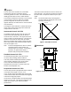
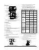
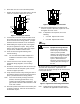
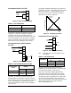
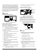
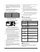
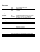
Table Of Contents

6 VA-715x Electric Valve Actuator Product/Technical Bulletin
In Direct Acting (DA) mode, an increasing signal will
cause the actuator drive screw to extend, pushing the
valve stem down. A decreasing signal will cause the
actuator drive screw to retract, pulling the valve stem
up. In Reverse Acting (RA) mode, a decreasing signal
will cause the actuator drive screw to extend, pushing
the valve stem down. An increasing signal will cause
the actuator drive screw to retract, pulling the valve
stem up (see Figure 2).
A
djustments
Feedback Control--VA-7153
1 2 3 R W S
Trimmer Knob
Feedback
Potentiometer
Figure 14: VA-7153 Feedback
Adjusting Feedback Resistance
With the actuator retracted (valve stem fully up), the
actuator is factory calibrated for 0 to 100 ohms
maximum across Terminals W and S.
Note: Feedback requirements may vary depending
upon application and controller calibration.
For example, to calibrate the actuator for 1000 ohms
at mid stroke (50% of travel):
1. Drive the valve so the actuator valve stem is in the
full up position.
2. Use an ohmmeter to measure the resistance
between Terminals W and S.
3. Adjust the trimmer knob until you read
20 to 40 ohms on the meter.
4. Drive the actuator so that the valve is in the full
down position.
5. Measure the resistance between Terminals W
and S with the ohmmeter.
6. Drive the actuator toward the center of its stroke
and stop when the resistance is 50% of the value
measured in Step 5.
7. Adjust the trimmer knob until you read 1000 ohms
on the meter.
Note: The actuator is now calibrated for 1000 ohms
at mid stroke (50% of travel).
8. Replace the cover and secure with the screw.
The unit is ready for operation.
Proportional Control--VA-7152
1 2 3 4
Zero Adjust
LED
I
np
u
t
Se
l
ection
Jumper
L
on
g/
S
ho
rt
Selection Jumper
Stroke
Po
t
en
t
io
meter
F
a
il
P
o
sition
D
ir
e
ct/Reverse
A
c
ti
on
Selection
Jum
pe
r
DA
RA
Figure 15: VA-7152 Components
Factory calibration is set for direct acting
1 to 9 VDC ±0.5 VDC for use with 0 to 10 VDC
controller and 5/16 in. stroke VT Series valve,
Push Down to Close (PDTC) applications. The signal
fail position jumper is factory positioned for fully up.
Note: The actuator will accept control signals of
20 VDC maximum with signals over 10 VDC
ignored by the actuator.
St
roke
L
S
Down
Up
0-10V
0-5V
5-10V
DA
RA
Figure 16: Jumpers
C
alibration
1. Set the input selection jumpers to match the
desired operating range. (See Figure 16.)
• Top Jumper = 0 to 10V
• Center Jumper = 0 to 5V
• Bottom Jumper = 5 to 10V
2. Set the short/long travel selection jumper:
• short for stroke lengths 1/2 in. or less
• long for strokes over 1/2 in.
3. Set the direct/reverse action jumper so that the
valve stem travels in the desired direction (per
changes in control signal).
• DA (Top Jumper) = stroke down on signal
increase
• RA (Bottom Jumper) = stroke up on signal
increase