
User Guide
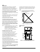
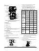
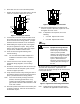
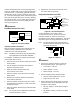
Table Of Contents

VA-715x Electric Valve Actuator Product/Technical Bulletin 7
4. Set the signal fail position jumper to select default
position of fully up or fully down. If the signal is
lost at the actuator (open connection), the actuator
will default to the pre-designated position of full up
or full down.
5. Apply voltage specified by application
requirements to drive the actuator to the full up
position using the following chart:
Table 5: VA-7152 Calibration Values
Application Values
Calibration Values
0-10
1-9
0-5
1-4
5-10
6-9
Note: Use of the calibration values in Table 5 will
ensure proper shutoff throughout the life of the
valve (accounts for seat wear).
• DA: full up (minimum voltage)
• RA: full up (maximum voltage)
1
2 3 4
Zero Adjust
LED
St
r
ok
e
Po
tentiome
t
er
RA
D
A
Figure 17: VA-7152 Adjustments
6. To ensure that the valve stem is in the full up
position, turn the zero adjust knob (shown in
Figure 17) completely to the left, until the valve
stem reaches the end of stroke.
7. Slowly turn the zero adjust knob to the right, and
stop as soon as the LED flashes or goes out.
Note: As the actuator is driving, the LED will be on.
The actuator circuit contains a time out
feature. If calibration takes longer than
3-10 minutes, the LED will go out giving a
false satisfied condition. If this occurs, turn off
the power, wait several seconds, turn the
power to the actuator back on, and then
readjust the zeroing knob.
8. Apply the input voltage specified by application
requirements to drive the valve stem to the full
down position per Table 5.
9. To ensure that the valve stem is in the full down
position, adjust the stroke potentiometer fully
Clockwise (CW) until the valve stem reaches the
end of stroke.
10. Slowly turn stroke potentiometer Counterclockwise
(CCW) until LED goes off.
11. Adjust voltage to drive actuator to the full up
position. Verify zero adjustment.
12. Check for proper operation using the desired
minimum and maximum operating voltages. Allow
the actuator to operate through several complete
cycles.
Note: The LED will remain on for 3-10 minutes after
the actuator has completed operation cycle.
13. Replace the cover and secure with the screw.
The unit is ready for operation.
O
rdering Information
To order a VA-715x Series Electric Actuator, specify
the complete product code number:
Table 6: Products Available
Code Number
Description
VA-7150-1001
Three Wire Incremental
VA-7153-1001
Three Wire Incremental with Position
Feedback
VA-7152-1001
Proportional, 0 to 10 VDC
Table 7: Accessories
Code Number
Description
V-9999-670
Bonnet Adapter used for field mounting
to VT Series valve body with threaded
stem
Y20EBE-2
Adapter Kit required to field mount
VT Series valve body with slotted stem
VA-7150-1900
Conduit Adapter Kit used to adapt
actuator Pg 9* threads to 1/2 in.
conduit
V-9999-BC1
Bonnet Adapter used for field mounting
to 1/2 to 1-1/4 in. VB-9xxx Series Siebe
(Barber-Colman) valves
V-9999-HW1
Bonnet Adapter used for field mounting
to V5011 A, F, G
1/2 to 3 in. single-seated and V5013F
three way Honeywell
valves
* European measurement for conduit threads
R
epair Information
Field repairs must not be made. For a replacement
actuator, contact the nearest Johnson Controls
representative.