
Install Instructions
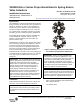
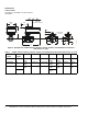
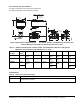
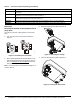
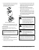
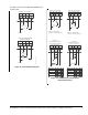
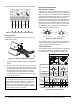
Table Of Contents

VA9208-GGx-x Series Proportional Electric Spring Return Valve Actuators Installation Instructions 3
Valve Actuator with Thermal Barrier
See Figure 3 and Table 2 for valve actuator dimensions
with optional M9000-561 Thermal Barrier installed.
Accessories
Table 2: VA9208 Actuated VG1241, VG1245, VG1841, and VG1845 Series Ball Valve with Optional
M9000-561 Thermal Barrier Installed Dimensions, in. (mm)
Valve Size
in. (DN)
Valve
Style
1
AB CDEFG
1-1/4 (DN32) All 9-17/64
(235)
1-1/32 (26) 1-23/32 (44) 7-1/4
(184)
3-15/16
(100)
11/32 (9) 1-31/32
(50)
1-1/2 (DN40) All 9-15/16
(240)
1-9/64 (29) 1-57/64 (48) 7-7/16
(189)
4-21/64
(110)
11/32 (9) 2-11/64
(55)
2 (DN50) 2-Way 9-31/32
(244)
1-15/32 (37) 2-1/8 (54) 7-11/16
(195)
4-24/32
(123)
11/32 (9) N/A
3-Way 7-7/8
(200)
2-27/64
(62)
1. Port A must always be connected to the coil (Figure 3).
Figure 3: Spring Return VA9208 Actuated VG1241, VG1245, VG1841, and VG1845 Series Ball Valve with
Optional M9000-561 Thermal Barrier Installed Dimensions, in. (mm)
3-29/32
(99)
A
B
3-1/2 (89)
Clearance Required
G
C
F
B
C
E
Port Marking
Locations
D
Table 3: Accessories (Order Separately)
Code Number Description
M9000-200 Commissioning Tool that Provides a Control Signal to Drive 24 V On/Off, Floating, Proportional, and/or
Resistive Electric Actuators