
Actuator Install Instructions
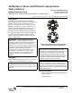
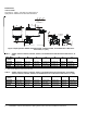
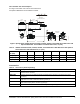
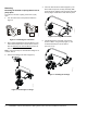

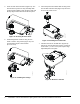
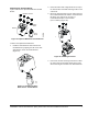
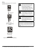
Table Of Contents

VA9203-Bxx-2 Series On/Off Electric Spring Return Valve Actuators Installation Instructions 9
Using Conduit
All VA9203 Series Actuators accept 1/2 in. threaded
electrician’s fittings (Figure 21).
1. Feed the actuator cables through the field-supplied
electrician’s fitting and conduit.
2. Thread the electrician’s fitting into the actuator and
secure the conduit to the fitting in accordance with
local building code requirements.
Setup and Adjustments
Auxiliary Switch (VA9203-xxB-xx Models)
The VA9203-xxB-xx models include one integral
auxiliary switch with a switch adjuster accessible on
either face of the actuator (Figure 22). The factory
setting for Auxiliary Switch is 10% closing (relative to
the 0 to 100% rotation range as printed on the product
label). See the Technical Specifications
section for the
auxiliary switch ratings.
The switch point is continuously adjustable throughout
the actuators’s rotation range. For the most accurate
switch positioning, see Figure 22 and use the method
in the following example. To change the switch point of
auxiliary switch, proceed as follows:
1. Position the actuator in the full spring return
position.
Note: The switch is factory set to trip when the
actuator reaches the 10% position.
2. Rotate the switch adjuster until it points to the
desired switch point.
3. Connect the auxiliary switch to a power source or
an ohmmeter and apply power to the actuator. The
actuator moves to the fully open position and holds
while power is applied.
4. Observe the switch point. If required, repeat Step 1
through Step 3.
Figure 21: Adding Flexible Metal Conduit
!
WARNING: Risk of Electric Shock and
Property Damage.
Insulate and secure each unused wire
lead before applying power to the
actuator. Failure to insulate and secure
each unused wire lead may result in
property damage, electric shock, and
severe personal injury or death.
Figure 22: Switch Trip Point Settings