
Actuator Install Instructions
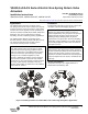

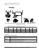

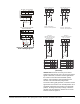
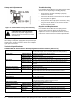
Table Of Contents

VA9104-xGA-3S Series Electric Non-Spring Return Valve Actuators Installation Instructions2
Dimensions
See Figure 2 for dimensions of the Non-Spring Return
VA9104 Actuated VG1241, VG1245, VG1841, and
VG1845 Series Ball Valve. See Table 1 for specific
model dimensions.
See Table 2 for specific model dimensions for the
VA9104 Actuated VG1275 and VG1875 Series Sweat
End and the VA9104 Actuated VG1295 and VG1895
Series Press End Connection Ball Valves.
Table 1: VA9104-xGx-3S Actuated VG1241, VG1245, VG1841, and VG1845 Series Ball Valve with Optional
M9000-551 Linkage Dimensions, in. (mm)
Valve Size,
in. (DN)
1
ABCDEFG
1/2 (DN15) 3-7/8 (98) 21/32 (17) 1-7/32 (31) 5-7/64 (129) 2-33/64 (64) 11/32 (9) 1-1/4 (32)
3/4 (DN20) 3-7/8 (98) 21/32 (17) 1-7/32 (31) 5-7/32 (133) 2-51/64 (71) 11/32 (9) 1-13/32 (36)
1 (DN25) 3-15/16 (100) 3/4 (19) 1-19/64 (33) 5-9/16 (141) 3-13/32 (87) 11/32 (9) 1-11/16 (43)
1. Port A must always be connected to the coil (Figure 2).
Table 2: VA9104 Actuated VG1275 and VG1875 Series Ball Valve with Sweat End Connections and VA9104
Actuated VG1295 and VG1895 Series Ball Valves with Press End Connections Dimensions,
in. (mm)
Valve Size,
in. (DN)
1
ABCDEFG
1/2 (DN15) 3-7/8 (98) 21/32 (17) 1-7/32 (31) 5-45/64 (145) 3-25/32 (96) 11/32 (9) 2-13/16 (55)
3/4 (DN20) 3-7/8 (98) 21/32 (17) 1-7/32 (31) 5-57/64(150) 4-3/32 (104) 11/32 (9) 2-15/32 (62)
1 (DN25) 3-15/16 (100) 3/4 (19) 1-19/64 (33) 6-1/8 (156) 4-21/32 (118) 11/32 (9) 2-27/32 (72)
1. Port A must connected to the coil (Figure 2).
Figure 2: VA9104 Series Electric Non-Spring Return Valve Actuator Dimensions, in. (mm)
Three-Way Valve
Two-Way Valve
Two-Way Valve
Three-Way Valve
Port Marking
Locations
B
6-1/16
(154)
B
A
F
C
C
Minimum Clearance Required
3-1/2 (89)
2-13/16
(71)