
Actuator Install Instructions
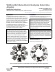

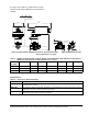

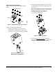
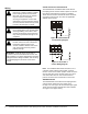
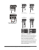
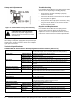
Table Of Contents

VA9104-xGA-3S Series Electric Non-Spring Return Valve Actuators Installation Instructions4
Mounting the Actuator
To mount the actuator:
1. Turn valve stem to position below.
2. Mount optional M9000-561 Thermal Barrier to the
valve if fluid temperature exceeds 212°F (100°C).
See the Mounting the Thermal Barrier
section for
more information.
3. Place the handle the top of the drive shaft
(Figure 5). The handle is keyed on and can only be
mounted in one orientation.
4. Check that the actuator coupler and handle are in
the full counterclockwise position as viewed from
the top of the actuator. If not, press the actuator
gear release and rotate the handle until the
actuator coupler is fully counterclockwise.
5. Install the valve actuator over the ball valve
mounting flange. Depending on the installation,
position the assembly in any one of four 90°
increments on the valve.
Note: For proper operation, the actuator must
drive the valve counterclockwise to open Port A
when viewed from above the valve
6. To secure the actuator to the valve, use a 1/4 in.
(6 mm) flat blade screwdriver. Recommended
torque is 8to12lbin (0.9 to 1.4 Nm).
Figure 4: Positioning the Valve Stem
F
I
G
:
V
G
1
0
0
0
3 Way2 Way
Figure 5: Installing the Handle
F
I
G
:
h
n
d
l
IMPORTANT: Do not overtighten the manual
handle mounting screw. Overtightening may strip
the threads resulting in damage to the valve stem
threads.
Figure 6: Coupling the Actuator to the Valve
F
I
G
:
C
U
P
L
A
C
T