
Actuator Install Instructions
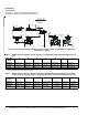
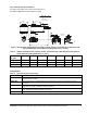
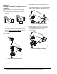
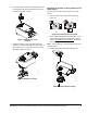
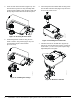
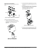
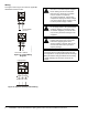
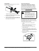
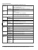
Table Of Contents

VA9203-Bxx-2 Series On/Off Electric Spring Return Valve Actuators Installation Instructions 3
Valve Actuator with Thermal Spacer
See Figure 3 and Table 3 for valve actuator dimensions
with optional M9000-561 Thermal Barrier installed.
Accessories
Table 3: VA9203 Actuated VG1241, VG1245, VG1841, and VG1845 Series NPT Ball Valve with Optional
Thermal Barrier Installed Dimensions, in. (mm)
Valve Size,
in. (DN)
1
ABC D EF G
1/2 (DN15) 6 (152) 21/32 (17) 1-7/32 (31) 6-31/32 (177) 2-33/64 (64) 11/32 (9) 1-1/4 (32)
3/4 (DN20) 6 (152) 21/32 (17) 1-7/32 (31) 7-1/8 (181) 2-51/64 (71) 11/32 (9) 1-13/32 (36)
1 (DN25) 6-1/16 (154) 3/4 (19) 1-19/64 (33) 7-31/64 (190) 3-13/32 (87) 11/32 (9) 1-45/64 (43)
1. Port A must always be connected to the coil.
Figure 3: Spring Return VA9203 Actuated VG1241, VG1245, VG1841, and VG1845 Series Ball Valve with
Optional M9000-561 Thermal Barrier Installed Dimensions, in. (mm)
Port Marking
Locations
F
I
G
:
V
A
9
2
0
3
X
_
d
i
m
s
t
h
b
r
2-7/8
(73)
3-1/4
(82)
A
D
3-1/2 (89)
Clearance Required
Table 4: Accessories (Order Separately)
Code Number Description
M9000-200 Commissioning Tool That Provides a Control Signal to Drive 24 V On/Off, Floating, Proportional, and/or
Resistive Electric Actuators
M9000-560 Ball Valve Linkage Kit for Applying M9203 and M9208 Series Actuators to VG1000 Series Valves
(Quantity 1)
M9000-561 Thermal Barrier Extends M(VA)9104, M(VA)9203, and M(VA)9208 Series Electric Spring Return Actuator
Applications to Include Low Pressure Steam (Quantity 1)
M9000-341 Weathershield Kit for VG1000 Series Ball Valve Application of M(VA)9104, M(VA)9203, and M(VA)9208
Series Electric Spring Return Actuators (Quantity 1)
M9000-607 Position Indicator for VG1000 Series Ball Valve Applications (Quantity 5)