
Actuator Install Instructions
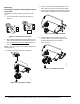
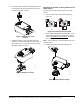
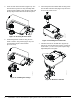
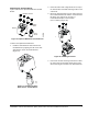
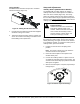
Table Of Contents

VA9203-Bxx-2 Series On/Off Electric Spring Return Valve Actuators Installation Instructions 7
Mounting the Thermal Barrier
Figure 16 shows the optional M9000-561 Thermal
Barrier.
To mount the optional thermal barrier:
1. Install the thermal barrier drive shaft into the
thermal barrier by aligning the tab on the drive
shaft with the slot on the thermal barrier
(Figure 17).
2. Rotate the drive shaft to align marks on the top of
the thermal drive shaft with matching marks on the
valve stem.
3. Mount the thermal barrier onto the valve using the
four included M5x16 mm machine screws and four
M5 flange nuts. Tighten the screws to a
recommended torque of 21 to 25 lb·in.
(2.4 to 2.8 N·m) (Figure 18).
4. Proceed to actuator mounting instructions. Follow
the same steps as mounting directly to the valve
when mounting the actuator to the thermal barrier.
Figure 16: Optional M9000-561 Thermal Barrier
Barrier
Drive
Shaft
Machine Screws
Flange
Nuts
Figure 17: Installing the Drive
Shaft into the Thermal Barrier
Figure 18: Installing the Barrier
F
I
G
:
i
n
_
a
c
t