
Actuator Install Instructions
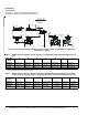
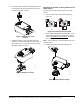
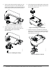
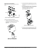
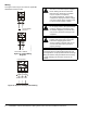
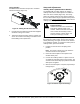
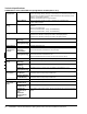
Table Of Contents

VA9203-Bxx-2 Series On/Off Electric Spring Return Valve Actuators Installation Instructions8
Wiring
See Figure 19 and Figure 20 to wire the applicable
VA9203-Bxx-2 Series model.
AC 85...264 V 50/60 Hz
L1N
WHT BLK
2
1
AC 24 V 50/60
DC 24 V
RED
BLK
2
1
+
-
~
F
I
G
:
V
A
9
2
0
3
B
x
x
2
_
w
i
r
i
n
g
Figure 19: Control Wiring
Diagrams
Figure 20: Optional Auxiliary Switch Wiring
5.0 (2.9) A 240 V
~
21
22
23
BLK/
RED
BLK/
BLU
BLK/
GRY
S1
21
23
22
21
COM
NC
NO
!
WARNING: Risk of Electric Shock.
Disconnect or isolate all power supplies
before making electrical connections.
More than one disconnect or isolation
may be required to completely
de-energize equipment. Contact with
components carrying hazardous voltage
can cause electric shock and may result
in severe personal injury or death.
!
CAUTION: Risk of Property Damage.
Do not apply power to the system before
checking all wiring connections. Short
circuited or improperly connected wires
may result in permanent damage to the
equipment.
!
CAUTION: Risk of Property Damage.
Insulate and secure each unused wire
lead before applying power to the
actuator. Failure to insulate and secure
each unused wire lead may result in
property damage.
IMPORTANT: Make all wiring connections in
accordance with the National Electrical Code and
local regulations. Use proper Electrostatic Discharge
(ESD) precautions during installation and servicing
to avoid damaging the electronic circuits of the
actuator.