
Valve Install Instructions
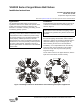
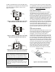
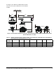
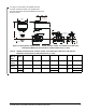
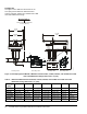
Table Of Contents

VG1000 Series Forged Brass Ball Valves Installation Instructions2
For more detailed installation information about the
specific equipment used, refer to the appropriate
document from the following list:
• VA9104-xGA-2S Series Electric Non-Spring Return
Valve Actuators Installation Instructions
(Part No. 14-1336-15)
• VA9104-xGA-3S Series Electric Non-Spring Return
Valve Actuators Installation Instructions
(Part No. 14-1336-23)
• M9102-AGA-2S and M9104-xGA-2S Series
Electric Non-Spring Return Actuators Installation
Instructions (Part No. 34-636-1220)
• M9102-AGA-3S and M9104-xGA-3S Series
Electric Non-Spring Return Actuators Installation
Instructions (Part No. 34-636-1433)
• M9106-xGx-2 Series Electric Non-Spring Return
Actuators Installation Instructions
(Part No. 34-636-1085)
• M9109 Series Electric Non-spring Return
Actuators Installation Instructions
(Part No. 34-636-1190)
• VA9203-AGx-2Z Series On/Off and Floating Point
Electric Spring Return Valve Actuators Installation
Instructions (Part No. 14-1380-8)
• VA9203-Bxx-2 Series On/Off Spring Return Valve
Actuators Installation Instructions
(Part No. 14-1380-16)
• VA9203-GGx-2Z Series Proportional Spring Return
Valve Actuators Installation Instructions
(Part No. 14-1380-24)
• VA9208-AGx-x Series On/Off and Floating Point
Electric Spring Return Valve Actuators Installation
Instructions (Part No. 14-1379-5)
• VA9208-Bxx-x Series On/Off Spring Return Valve
Actuators Installation Instructions
(Part No. 14-1379-13)
• VA9208-GGx-x Series Proportional Spring Return
Valve Actuators Installation Instructions
(Part No. 14-1379-21)
• M9108, M9116, M9124, and M9132 Series Electric
Non-Spring Return Actuators Installation
Instructions (Part No. 34-636-399)
• M9210-AGx-3 Floating Electric Spring Return
Actuators Installation Instructions
(Part No. 34-636-1654)
• M9210-Bxx-3 On/Off Electric Spring Return
Actuators Installation Instructions
(Part No. 34-636-1638)
• M9210-GGx-3 Proportional Electric Spring Return
Actuators Installation Instructions
(Part No. 34-636-1662)
• M2000-560 Ball Valve Linkage Kit and M9000-561
Thermal Barrier Installation Instructions
(Part No. 34-636-2227)
• M9000-330 and M9000-340 Series Weather Shield
Enclosures Installation Instructions
(Part No. 14-1330-26)
• M9000-341 Series Weather Shield Enclosures
Installation Instructions (Part No. 34-636-2235)
• M9000-51x Series Valve Linkage Kits Installation
Instructions (Part No. 14-1201-13)
• M9000-520 Ball Valve Linkage Kit Installation
Instructions (Part No. 14-1297-5)
• M9000-551 Ball Valve Linkage Kit Installation
Instructions (Part No. 34-636-1816)
Note: To avoid excessive wear or drive time on the
motor for VA9104, M9104, M9106, and M9109 AGx
models, use a controller and/or software that provides
a time-out function to remove the signal at the end of
rotation (stall). The IGx and GGx models have an auto
shutoff to avoid excessive wear or drive time on the
motor.
On models with the flow-characterizing disk, the disk is
located in Port A. Port A must be the inlet. On
three-way models, use Port A as the coil inlet and
Port B as the bypass inlet.
IMPORTANT: Take care to prevent foreign material
such as weld slag, thread burrs, metal chips, and
scale from entering the piping system. This debris
can damage or severely impede the operation of the
valve by embedding itself in the seats, scoring the
valve, and ultimately resulting in seat leakage. If the
debris becomes embedded in the seats, subsequent
flushing and filtering of the piping system with the
valve installed does not remedy the problem.