
Valve Install Instructions
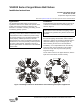
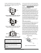
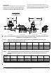
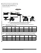
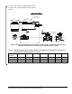
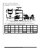
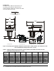
Table Of Contents

VG1000 Series Forged Brass Ball Valves Installation Instructions 3
VG1841 and VG1845 Series Three-Way Ball Valves
have a different port configuration from VG1644 Series
Three-Way valves. See Figure 2, Figure 3, and
Figure 4 for details.
Contact your local Johnson Controls® representative
for compatibility concerns before using VG1000 Series
Ball Valves to control the flow of fluids other than those
outlined in the Technical Specifications
table in this
document.
Press Valve Installation
VG1000 press end connection valves are installed
using RIDGID® press tools. Always refer to the
operator’s manual supplied with the RIDGID press tool
that is used to make the valve end connections. The
manual should provide proper instructions for the safe
operation of the tool, proper crimping procedures, and
methods of inspecting the finished connection. If you
use a battery-operated press tool, ensure its proper
operation by fully charging the unit. To avoid damage to
the integral O-ring, never use sealant or pipe dope with
a press connection. Always inspect the end
connections of the valve before making the connection.
The end connection should not be deformed, and the
internal, integral O-ring must be in place for a proper
seal.
Sweat Valve Installation
When soft soldering sweat ball valves, be sure to use a
low temperature solder with a melting point that does
not exceed 450°F (232°C). For lead-free RoHS
compliance, a 96.5% tin/3.5% silver solder is
recommended. Never install the actuator on the valve
until you have completed the soldering operation and
the valve body has cooled. Before soldering, minimize
the risk of damage to the ball seals by positioning the
ball so that Port A is fully open. When soldering, always
apply a wet rag around the valve’s neck and cover as
much of the valve body with the rag as possible. Direct
the tip of the flame away from the valve and always
heat the copper tubing directly, but never the valve
body. Solder Port A first, then the remaining ports.
These steps provide maximum protection to the
internal valve components. See Figure 5 for details.
IMPORTANT: Protect the actuator from dripping
water, condensation, and other moisture. Water or
moisture could result in an electrical short, which
may damage or affect the operation of the actuator.
IMPORTANT: Do not cover the actuator with
thermal insulating material. High ambient
temperatures may damage the actuator, and a hot
water pipe, steam pipe, or other heat source may
overheat it.
F
I
G
:
V
G
A
t
o
C
Port A
Coil
Port C
Common
Port B Bypass
Figure 2: VG1841 or VG1845 Series Three-Way
Ball Valve (Port A Connected to Port C)
Port A
Coil
Port C
Common
Port B Bypass
F
I
G
:
v
g
B
t
o
C
Figure 3: VG1841 or VG1845 Series Three-Way
Ball Valve (Port B Connected to Port C)
Common
Port
Normally
Open Port
Normally
Closed Port
F
I
G
:
v
g
1
6
4
4
c
c
w
Figure 4: Top View of VG1644 Series Three-Way
Ball Valve (Actuator Fully Counterclockwise)
Figure 5: Sweat Valve Installation
Use only low meltin
g
temperature soft solder.
Place wet rag
around neck of valve.
FIG:sv_inst