
Valve Install Instructions
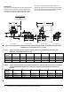
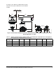
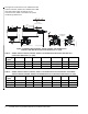
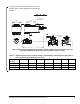
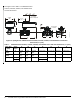
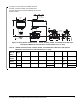
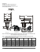
Table Of Contents

VG1000 Series Forged Brass Ball Valves Installation Instructions4
Dimensions
See Figure 6 for dimensions of the Non-Spring Return
VA9104 Actuated VG1241, VG1245, VG1841, and
VG1845 Series Ball Valve with M9000-551 Linkage.
See Table 1 for specific model linkage dimensions.
See Table 2 for specific model dimensions for the
VA9104 Actuated VG1275 and VG1875 Series Sweat
End and the VA9104 Actuated VG1295 and VG1895
Series Press End Connection Ball Valves.
Table 1: VA9104 or M9104 Actuated VG1241, VG1245, VG1841, and VG1845 Series Ball Valve with
M9000-551 Linkage Dimensions, in. (mm)
Valve Size,
in. (DN)
1
ABCDEFG
1/2 (DN15) 3-7/8 (98) 21/32 (17) 1-7/32 (31) 5-7/64 (129) 2-33/64 (64) 11/32 (9) 1-1/4 (32)
3/4 (DN20) 3-7/8 (98) 21/32 (17) 1-7/32 (31) 5-7/32 (133) 2-51/64 (71) 11/32 (9) 1-13/32 (36)
1 (DN25) 3-11/16 (100) 3/4 (19) 1-19/64 (33) 5-9/16 (141) 3-13/32 (87) 11/32 (9) 1-11/16 (43)
1. On models with the flow-characterizing disk, the disk is located in Port A. Port A must be the inlet.
Table 2: VA9104 Actuated VG1275 and VG1875 Series Ball Valve with Sweat End Connections and VA9104
Actuated VG1295 and VG1895 Series Ball Valves with Press End Connections Dimensions,
in. (mm)
Valve Size,
in. (DN)
1
ABCDEF
1/2 (DN15) 3-7/8 (98) 21/32 (17) 1-7/32 (31) 5-45/64 (145) 3-25/32 (96) 2-13/16 (55)
3/4 (DN20) 3-7/8 (98) 21/32 (17) 1-7/32 (31) 5-57/64(150) 4-3/32 (104) 2-15/32 (62)
1 (DN25) 3-11/16 (100) 3/4 (19) 1-19/64 (33) 5-1/8 (156) 3-13/32 (118) 2-27/32 (72)
1. On models with the flow-characterizing disk, the disk is located in Port A. Port A must be the inlet.
Figure 6: Non-Spring Return VA9104 Actuated VG1241, VG1245, VG1841, and VG1845 Series Ball Valve
with M9000-551 Linkage Dimensions, in. (mm)
E
D
Minimum Clearance Required
3-1/2 (89)
A
B
C
G
Three-Way Valve
B
E
C
F
Three-Way Valve Two-Way ValveTwo-Way Valve
F
I
G
:
v
g
1
k
v
a
0
4
5-1/2
(140)
2-13/16
(71)