
Valve Install Instructions
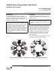
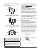
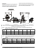
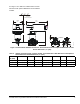
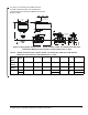

Table Of Contents

VG1000 Series Forged Brass Ball Valves Installation Instructions 1
Refer to the QuickLIT Web site for the most up-to-date version of this document.
Applications
The VG1000 Series Ball Valves are designed to
regulate the flow of hot or chilled water (and for some
models, low pressure steam) in response to the
demand of a controller in Heating, Ventilating, and Air
Conditioning (HVAC) systems.
Installation
Install VG1000 Series Ball Valves with the actuator at
or above the centerline of the horizontal piping, as
shown in Figure 1.
To minimize heat transfer in steam applications, wrap
the valve and piping with insulation. Allow sufficient
clearance to remove the actuator (as illustrated in the
dimension drawings, Figure 6 through Figure 15).
When mounting the actuator in the field (before
installation), use an adjustable wrench to manually
rotate the valve stem several times. This rotation
breaks the torque that may have built up during
long-term storage.
For the valve to move in the proper direction, wire the
input lines to the electric actuator correctly.
IMPORTANT: Use the VG1000 Series Valves as an
operating control. Where failure or malfunction of the
VG1000 Series Valve could lead to personal injury
or property damage to the controlled equipment or
other property, additional precautions must be
designed into the system. Incorporate and maintain
other devices, such as supervisory or alarm systems
or safety or limit controls, intended to warn of or
protect against failure or malfunction of the VG1000
Series Valve.
IMPORTANT: In steam applications, install the
valve with the stem horizontal to the piping. Failure
to follow these guidelines may shorten the life of the
actuator.
Figure 1: Mounting Positions for Chilled Water and Condensing Atmosphere Applications
F
I
G
:
m
n
t
p
o
s
VG1000 Series Forged Brass Ball Valves
Installation Instructions
Part No. 14-1201-5, Rev. R
Issued June 9, 2011
Supersedes August 26, 2008