
Valve Install Instructions
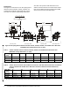
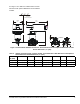
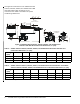
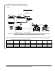
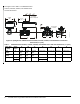
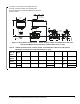

Table Of Contents

VG1000 Series Forged Brass Ball Valves Installation Instructions6
See Figure 8 for dimensions of the VA9203 Actuated
VG1241, VG1245, VG1841, and VG1845 Series Ball
Valve with National Pipe Thread (NPT) end
connections. See Table 4 and Table 5 for specific
model linkage dimensions.
Table 4: VA9203 Actuated VG1241, VG1245, VG1841, and VG1845 Series Ball Valve with NPT End
Connections Dimensions, in. (mm)
Valve Size,
in. (DN)
1
ABCDE FG
1/2 (DN15) 4-1/4 (108) 21/32 (17) 1-7/32 (31) 6-23/32 (171) 2-33/64 (64) 11/32 (9) 1-1/4 (32)
3/4 (DN20) 4-1/4 (108) 21/32 (17) 1-7/32 (31) 6-7/8 (175) 2-51/64 (71) 11/32 (9) 1-13/32 (36)
1 (DN25) 4-9/32 (109) 3/4 (19) 1-19/64 (33) 7-7/64 (181) 3-13/32 (87) 11/32 (9) 1-45/64 (43)
1. Port A must always be connected to the coil.
Table 5: VA9203 Actuated VG1271, VG1275, VG1871, and VG1875 Series Sweat Ball Valve and VA9203
Actuated VG1291, VG1295, VG1891, and VG1895 Series Press Ball Valve Dimensions, in. (mm)
Valve Size,
in. (DN)
1
ABC D EFG
1/2 (DN15) 4-5/8 (117) 21/32 (17) 1-7/32 (31) 7-13/64 (183) 3-25/32 (96) 11/32 (9) 1-1/4 (32)
3/4 (DN20) 4-5/8 (117) 21/32 (17) 1-7/32 (31) 7-3/4 (197) 4-3/32 (104) 11/32 (9) 1-13/32 (36)
1 (DN25) 4-11/16 (119) 3/4 (19) 1-19/64 (33) 8-3/16 (208) 4-41/64 (118) 11/32 (9) 1-45/64 (43)
1. Port A must always be connected to the coil.
Figure 8: VA9203 Actuated VG1241, VG1245, VG1841, and VG1845 Series
Ball Valve with NPT End Connections Dimensions, in. (mm)
Port Marking
Locations
F
I
G
:
V
A
9
2
0
3
X
_
d
i
m
s
3-1/4
(82)
D
A
3-1/2 (89)
Clearance Required
2-7/8
(73)