
Valve Install Instructions
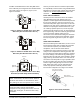
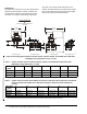
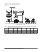
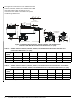
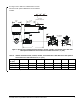
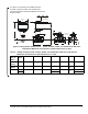
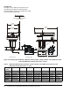
Table Of Contents

VG1000 Series Forged Brass Ball Valves Installation Instructions 7
See Figure 9 and Table 6 for VA9203 Valve Actuator
dimensions with optional M9000-561 Thermal Barrier
installed.
Table 6: VA9203 Actuated VG1241, VG1245, VG1841, and VG1845 Series NPT Ball Valve with Optional
Thermal Barrier Installed Dimensions, in. (mm)
Valve Size
in. (DN)
1
ABCDEFG
1/2 (DN15) 6 (152) 21/32 (17) 1-7/32 (31) 6-31/32 (177) 2-33/64 (64) 11/32 (9) 1-1/4 (32)
3/4 (DN20) 6 (152) 21/32 (17) 1-7/32 (31) 7-1/8 (181) 2-51/64 (71) 11/32 (9) 1-13/32 (36)
1 (DN25) 6-1/16 (154) 3/4 (19) 1-19/64 (33) 7-31/64 (190) 3-13/32 (87) 11/32 (9) 1-45/64 (43)
1. Port A must always be connected to the coil.
Port Marking
Locations
F
I
G
:
V
A
9
2
0
3
X
_
d
i
m
s
t
h
b
r
2-7/8
(73)
3-1/4
(82)
A
D
3-1/2 (89)
Clearance Required
Figure 9: Spring Return VA9203 Actuated VG1241, VG1245, VG1841, and VG1845 Series Ball Valve
with Optional M9000-561 Thermal Barrier Installed Dimensions, in. (mm)