
Valve Install Instructions
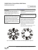
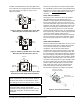
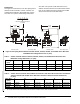
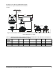
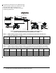
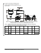
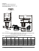
Table Of Contents

VG1000 Series Forged Brass Ball Valves Installation Instructions 5
See Figure 7 and Table 3 for VA9104 Valve Actuator
dimensions with optional M9000-561 Thermal Barrier
installed.
Table 3: VA9104 Actuated VG1241, VG1245, VG1841, and VG1845 Series NPT Ball Valves with Optional
Thermal Barrier Installed Dimensions, in. (mm)
Valve Size,
in. (DN)
1
ABCD EFG
1/2 (DN15) 5-11/32 (135) 21/32 (17) 1-7/32 (31) 5-7/64 (129) 2-33/64 (64) 11/32 (9) 1-1/4 (32)
3/4 (DN20) 5-11/32 (135) 21/32 (17) 1-7/32 (31) 5-7/32 (133) 2-51/64 (71) 11/32 (9) 1-13/32 (36)
1 (DN25) 5-27/64 (137) 3/4 (19) 1-19/64 (33) 5-9/16 (141) 3-13/32 (87) 11/32 (9) 1-11/16 (43)
1. On models with the flow-characterizing disk, the disk is located in Port A. Port A must be the inlet.
Figure 7: Field-Installed VA9104 Series Electric Actuator Dimensions with Optional M9000-561 Thermal
Barrier Dimensions, in. (mm)
2-13/16
(71)
3-1/2 (89)
Clearance Required
Port Marking
Locations
F
I
G
:
M
9
1
0
4
X
_
d
i
m
s
5-1/2
(140)
D
A