
Actuator Install Instructions
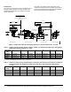
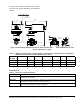
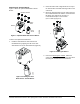
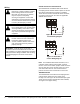
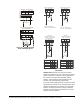
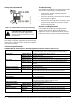
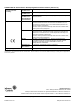
Table Of Contents

VA9104-xGA-3S Series Electric Non-Spring Return Valve Actuators Installation Instructions6
Wiring
VA9104-AGA-3S and VA9104-IGA-3S
The VA9104-AGA and VA9104-IGA Series Electric
Non-Spring Return Valve Actuators require an AC 24 V
input signal and work with a variety of controllers.
These electric actuators include M3 Screw terminals;
see Figure 10 and Figure 11 to wire the applicable
VA9104 Series model.
Note: For all VA9104-AGA Series Actuators, use a
controller and/or software that provides a timeout
function at the end of rotation (stall) to avoid excessive
wear or drive time on the actuator motor. The -GGA
and -IGA models have an auto shutoff feature to
prevent excessive wear or drive time on the motor.
VA9104-GGA-3S
The VA9104-GGA Series Electric Non-Spring Return
valve actuators require AC 24 V power and a
DC 0(2) to 10 V or 0(4) to 20 mA controller input signal.
These electric actuators include M3 screw terminals;
see Figure 12 for proper wiring.
!
WARNING: Risk of Electric Shock.
Disconnect or isolate all power supplies
before making electrical connections.
More than one disconnect or isolation
may be required to completely
de-energize equipment. Contact with
components carrying hazardous voltage
can cause electric shock and may result
in severe personal injury or death.
!
CAUTION: Risk of Property Damage.
Do not apply power to the system before
checking all wiring connections. Short
circuited or improperly connected wires
may result in permanent damage to the
equipment.
!
CAUTION: Risk of Property Damage.
Insulate and secure each unused wire
lead before applying power to the
actuator. Failure to insulate and secure
each unused wire lead may result in
property damage.
IMPORTANT: Make all wiring connections in
accordance with the National Electrical Code and
local regulations. Use proper Electrostatic Discharge
(ESD) precautions during installation and servicing
to avoid damaging the electronic circuits of the
actuator.
~~
AC 24 V 50/60 Hz
321
~
Figure 10: VA9104-AGA-3S
Control Wiring Diagram
~~
AC 24 V 50/60 Hz
3
~
12
Figure 11: VA104-IGA-3
Control Wiring Diagram