
Actuator Install Instructions
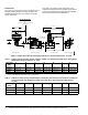
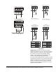
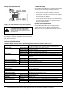
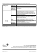
Table Of Contents

VA9104-xGA-3S Series Electric Non-Spring Return Valve Actuators Installation Instructions 7
VA9104-GGA actuators are factory set for Direct
Acting (DA) mode and for a DC 0 to 10 V input control
signal. In DA mode, a minimum control signal drives
the actuator to the full Counterclockwise (CCW)
position, and a maximum control signal drives the
actuator to the full Clockwise (CW) position.
For Reverse Acting (RA) operation, a minimum control
signal drives the actuator to the full CW position and a
maximum signal drives the actuator to the full CCW
position. To change the factory settings, remove the
actuator cover and adjust the switches on the circuit
board as shown in Figure 14.
Figure 12: VA9104-GGA-3S
Control Wiring Diagram
+
213
AC
24 V
0(2)...10 V
Y
DC 0(2)...10 V Control
~
DC 0(2)...10 V
~
0(4)...20 mA Control with
External Resistor
21
0(4)...20 mA
3
AC
24 V
0(2)...10 V
Y
~
~
+
Figure 13: VA9104-GGA Control Wiring Diagram
(Overrides)
1
2
3
~
Y
COM
BLK
RED GRY
+
Override to MIN position
AC
24 V
DC 0(2)...10 V
A
A Open = MIN Position
A Closed = Normal Operation
1
2
3
~
Y
COM
BLK
RED GRY
+
Override to MAX position
AC
24 V
DC 0(2)...10 V
C
B Closed = MAX Position
C Closed = Normal Operation
B
1
2
3
~
COM
BLK
RED GRY
+
Override to
MIN, MID, MAX positions
0(4)...20 mA Control with
External Resistor
AC
24 V
A
0(4)...20 mA
500 / 0.25 W
B
C
12
3
~
COM
BLK
RED
GRY
+
Override to
MIN, MID, MAX positions
0(2)...10 V Control
AC
24 V
A
B
C
DC
0
(
2
)
...10 V
Y
F
U
N
C
T
I
O
N
A
B
C
0% ( MIN )
50% ( MID )
100% ( MAX )
NORMAL
F
U
N
C
T
I
O
N
A
B
C
0% ( MIN
︶
50% ( MID )
100% ( MAX )
NORMAL
Y
Ω
FIG:VA9104GGx2(Z)_wir