
Install Instructions
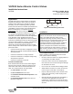
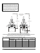
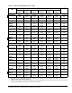
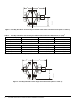
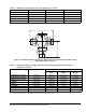

Table Of Contents

VG7000 Series Bronze Control Valves Installation Instructions 1
Applications
VG7000 Series Bronze Control Valves are primarily
designed to regulate the flow of water and steam in
response to the demand of a controller in Heating,
Ventilating, and Air Conditioning (HVAC) systems.
Contact the local Johnson Controls® representative for
compatibility concerns before using VG7000 Series
Bronze Control Valves to control the Technical
Specifications table at the end of this document.
The installation instructions included here conform to
the relevant and valid European Norm (EN) safety
standards, as well as the current laws and regulations
of the European Union. Qualified personnel are
required for the proper application of these installation
instructions. Qualified personnel are defined as people
conversant with installation, mounting, commissioning,
operation, and servicing of pneumatically and
electrically actuated VG7000 Series Bronze Control
Valves, through their activities and functions. Qualified
personnel include:
• trainers and instructors with an obligation to ensure
adherence to regional and international ordinances
and requirements
• trainers and instructors of safety standards
• trainers and instructors of adequate facility safety
and protective operation
• trainers and instructors of first aid
Location of Valve Data
Each VG7000 Series Bronze Control Valve shipped
from the factory includes a brass tag chained to the
valve bonnet that features technical data about the
valve. The technical data on the tag includes:
•the code number of the valve
•the flow coefficient Cv of the valve
•the maximum allowable fluid temperature of the
controlled media
•the manufacturing date code of the valve (as
illustrated in Figure 1)
Installation
Pre-installation Details
Before installing a VG7000 Series Bronze Control
Valve, please note the following:
• Be sure to mount the valve in an upright position, in
a conveniently accessible location.
• Protect the electric actuator from dripping water
that could enter the actuator housing and damage
the mechanism or motor.
• Do not cover the actuator with insulating material.
• Allow sufficient clearance to remove the actuator
(refer to Figure 2 and Table 1 and Table 2).
• Pipe the valve with the flow in the direction of the
arrow on the valve body, so that the plug seats
against the flow.
• Wire all electrically actuated valve assemblies in
accordance with applicable electrical code
requirements. Input lines to the actuator must be
wired correctly for the valve to move in the proper
direction.
IMPORTANT: The VG7000 Series Bronze Control
Valves are intended to control saturated steam, hot
water, and chilled water flow under normal
equipment operating conditions. Where failure or
malfunction of the VG7000 Series Valve could lead
to personal injury or property damage to the
controlled equipment or other property, additional
precautions must be designed into the control
system. Incorporate and maintain other devices
such as supervisory or alarm systems or safety or
limit controls, intended to warn of or protect against
failure or malfunction of the VG7000 Series Valve.
Manufacturing Facility
w wy y
M
Week
Year
fig:mfgdtcd
Figure 1: Manufacturing Date Code
VG7000 Series Bronze Control Valves
Installation Instructions
VG7000
Part No. 14-1078-6, Rev. E
Issued June 16, 2008
Supersedes August 12, 2002