
Install Instructions
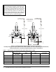
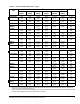
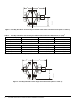
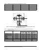
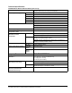

Table Of Contents

VG7000 Series Bronze Control Valves Installation Instructions2
Dimensions
IMPORTANT: Take care to prevent foreign material
such as weld slag, thread burrs, metal chips, and
scale from entering the piping system. This debris
can damage or severely impede the operation of the
valve by embedding itself in the seats, scoring the
valve, and ultimately resulting in seat leakage. If the
debris becomes embedded in the seats, subsequent
flushing and filtering of the piping system with the
valve installed does not remedy the problem.
Table 1: National Pipe Thread (Internal NPT) Valve Dimensions, in. (mm)
Valve Size, in. (DN) A B
N.O., N.C., and
Three-Way
N.O. N.C. Three-Way
1/2 (DN15) 3 (76) 13/16 (21) 1-9/16 (39) 1-13/16 (46)
3/4 (DN20) 3-7/32 (81) 15/16 (24) 1-5/8 (41) 2-1/8 (54)
1 (DN25) 4-1/8 (104) 1-5/32 (29) 1-3/4 (44) 2-9/16 (65)
1-1/4 (DN32) 4-23/32 (119) 1-11/32 (34) 2 (51) 2-25/32 (70)
1-1/2 (DN40) 5-1/8 (130) 2-5/32 (55) 2-3/4 (70) 3-3/8 (85)
2 (DN50) 5-29/32 (150) 2-1/8 (53) 2-27/32 (72) 3-3/4 (95)
A
D
Outlet
Inlet
B
C
Valve + Actuator
A
D
B
C
Valve + Actuator
Clearance Needed
for Actuator Mounting
and Removal
N.O.
(PDTC)
N.C.
(PDTC)
Fig:VG7000
Figure 2: Two-Way Normally Open (N.O.)/Push Down to Close (PDTC),
Two-Way Normally Closed (N.C.)/Push Down to Open (PDTO), and Three-Way Mixing Valve Dimensions,
Fluid Flow Directions, and Port Designations (Refer to Table 1 and Table 2.)