
User's Manual Part 3


GPS Motor Control
minnkotamotors.com
46
UNDERSTANDING HOW
THE I-PILOT LINK NAVIGATION WORKS
i-Pilot Link uses GPS satellite signals as well as digital compass data to know where it is, where it is heading and the
direction the motor is pointing. Since i-Pilot Link depends on GPS satellite signals for navigation, a minimum GPS
signal level of one bar is required in order for GPS navigation controls to be enabled. Best results are achieved when a
GPS signal level of four bars can be obtained.
In simple terms, i-Pilot Link remembers and creates points to navigate your boat automatically. i-Pilot Link also uses
a method of GPS navigation called arrival circles. These imaginary circles allow i-Pilot Link to understand when it has
drifted away from a point and when it has arrived at a point. The size of the arrival circles vary depending on GPS signal
strength, thus the greater the signal strength the smaller the arrival circles.
overview - USinG i-Pilot link froM the Control head
The i-Pilot Link allows you to start navigation commands from the Humminbird control head and start
navigation with the i-Pilot Link. The commands from the remote will also be displayed on the control head.
The i-Pilot Link features are displayed in Chart View and Bird’s Eye View. The control head uses the data from the GPS
Receiver attached directly to it or within the Ethernet network.
Some of the i-Pilot Link navigation functions may override traditional Humminbird navigation menu options. The alarms
have also been adapted to the i-Pilot Link.
You will need the actions in this section throughout the manual.
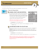
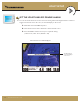
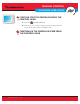
Using Side Imaging/Chart View with the i-Pilot Link
i-Pilot Link
Icon indicates
i-Pilot Link
navigation is in
progress (to the
next Waypoint in
the route)
Side Imaging View Chart View
Spot-Lock Icon
Propeller Icon
will spin when the i-Pilot Link
prop is spinning