
User's Manual


16
minnkot amotor s.com
INSTALLATION
FIGURE 22
FIGURE 26FIGURE 25
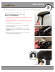
Zip Tie
Location 1
Zip Tie
Location 2
Zip Tie
Location 3
FIGURE 24
FIGURE 23
9. Install new grommet supplied with i-Pilot Link by snapping it into
the hole located in front of the coil cord strain relief. The i-Pilot
Link controller cable must be placed in the pass-through slot of
the grommet. (Figure 22)
10. Place the i-Pilot Link controller where the control box cover
was installed. Pull any extra controller cable out of the control
box by gently pulling on the cable. (Figure 23)
11. Secure cover with supplied #8 screws. Do not over tighten
screws. (Figure 24)
12. Secure the i-Pilot Link controller cable to the motor coil cord
in all three locations shown using zip ties provided. (Figure 25)
Trim zip ties using utility knife. Failure to secure cable will result
in possible damage to the cabling during operation.
13. Remove the left and right side plates of trolling motor by
loosening all four side plate screws using a Phillips screwdriver
(Figure 26)