Operator′s manual Please read the operator’s manual carefully and make sure you understand the instructions before using the machine.
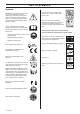
KEY TO SYMBOLS Symbols Only use non-metallic, flexible cutting attachments, i.e. trimmer heads with trimmer cord. WARNING! A clearing saw, brushcutter or trimmer can be dangerous if used incorrectly or carelessly, and can cause serious or fatal injury to the operator or others. It is extremely important that you read and understand the contents of this operator’s manual. Noise emission to the environment according to the European Community’s Directive.
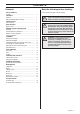
CONTENTS Contents KEY TO SYMBOLS Symbols ....................................................................... CONTENTS Contents ...................................................................... Note the following before starting: ................................ INTRODUCTION Dear Customer, ............................................................ WHAT IS WHAT? What is what? .............................................................. GENERAL SAFETY PRECAUTIONS Impor tant .......................
INTRODUCTION Dear Customer, Congratulations on your choice to buy a Jonsered product! We are convinced that you will appreciate with great satisfaction the quality and performance of our product for a very long time to come. The purchase of one of our products gives you access to professional help with repairs and service whenever this may be necessary. If the retailer who sells your machine is not one of our authorised dealers, ask for the address of your nearest service workshop.
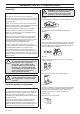
WHAT IS WHAT? 1 2 3 7 10 9 11 12 8 4 5 16 14 15 6 32 20 13 17 25 21 18 26 30 19 27 22 28 31 23 29 24 5 4 What is what? 1 Trimmer head 17 Air purge 2 Bevel gear 18 Air filter cover 3 Grease filler cap, bevel gear 19 Fuel tank 4 Cord cutter 20 Starter handle 5 Cutting attachment guard 21 Transport guard 6 Guard extension 22 Socket spanner 7 Shaft 23 Spanner 8 Handle adjustment 24 Locking pin 9 Throttle control 25 Locking nut 10 Stop switch 26 Support flange 1
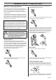
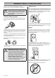
GENERAL SAFETY PRECAUTIONS Important IMPORTANT! The machine is only designed for trimming grass. The only accessories you can operate with this engine unit are the cutting attachments we recommend in the chapter on Technical data. ! WARNING! Listen out for warning signals or shouts when you are wearing hearing protection. Always remove your hearing protection as soon as the engine stops.
GENERAL SAFETY PRECAUTIONS Machine′s safety equipment Press the throttle lockout and make sure it returns to its original position when you release it. This section describes the machine′s safety equipment, its purpose, and how checks and maintenance should be carried out to ensure that it operates correctly. See the ”What is what?” section to locate where this equipment is positioned on your machine.
GENERAL SAFETY PRECAUTIONS Always use the recommended guard for the cutting attachment you are using. See chapter on Technical data. ! WARNING! Never use a cutting attachment without an approved guard. See the chapter on Technical data. If an incorrect or faulty guard is fitted this can cause serious personal injury.
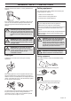
GENERAL SAFETY PRECAUTIONS Regularly check that the muffler is securely attached to the machine. Cutting equipment This section describes how to choose and maintain your cutting equipment in order to: If the muffler on your machine is fitted with a spark arrestor mesh this must be cleaned regularly. A blocked mesh will cause the engine to overheat and may lead to serious damage. ! ! ! WARNING! Mufflers fitted with catalytic converters get very hot during use and remain so for some time after stopping.
GENERAL SAFETY PRECAUTIONS Keep the teeth of the blade correctly sharpened! Follow our instructions and use the recommended file gauge. An incorrectly sharpened or damaged blade increases the risk of accidents. Trimmer head IMPORTANT! Always ensure the trimmer cord is wound tightly and evenly around the drum, otherwise the machine will generate harmful vibration. • Only use the recommended trimmer heads and trimmer cords. These have been tested by the manufacturer to suit a particular engine size.
ASSEMBLY Fitting the main body Connect the engine (A) to the tube (B) with four screws (C). A Connecting throttle cable and stop switch wires 1 Remove the air filter cover. 2 Insert the throttle cable (A) through the carburettor bracket (B), then screw the cable adjuster sleeve (C) into the carburettor bracket fully. 3 Position the slotted fitting (D) on the carburettor so the recessed hole (E) for the cable lug (F) is away from the cable adjuster sleeve.
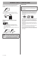
ASSEMBLY 9 Lap and fix the stop switch wires and connectors with clamp (I). Fitting a blade guard, grass blade and grass cutter I • Fit the guard (A) to the gear housing using the support plate (M) and two screws (L). B L C M 10 Refit the air filter cover. A Assembling the cutting equipment ! WARNING! When fitting the cutting attachment it is extremely important that the raised section on the drive disc/support flange engages correctly in the centre hole of the cutting attachment.
ASSEMBLY Fitting other guards and cutting attachments Standard harness Quick release • Fit the guard (A) to the gear housing using the support plate (M) and two screws (L). B At the front is an easily accessible, quick release. Use this if the engine catches fire or in any other emergency situation that requires you to free yourself from the machine and harness. L C M A • Fit the drive disc (B) on the output shaft.
FUEL HANDLING Fuel safety Petrol Never start the machine: 1 If you have spilt fuel on it. Wipe off the spillage and allow remaining fuel to evaporate. 2 If you have spilt fuel on yourself or your clothes, change your clothes. Wash any part of your body that has come in contact with fuel. Use soap and water. 3 If the machine is leaking fuel. Check regularly for leaks from the fuel cap and fuel lines. NB! Always use a quality petrol/oil mixture at least 90 octane (RON).
FUEL HANDLING Fuelling Mixing • Always mix the petrol and oil in a clean container intended for fuel. • Always start by filling half the amount of the petrol to be used. Then add the entire amount of oil. Mix (shake) the fuel mixture. Add the remaining amount of petrol. • ! Mix (shake) the fuel mixture thoroughly before filling the machine’s fuel tank. WARNING! Taking the following precautions, will lessen the risk of fire: Do not smoke or place hot objects near fuel.
STARTING AND STOPPING Check before starting • Check the blade to ensure that no cracks have formed at the bottom of the teeth or by the centre hole. The most common reason why cracks are formed is that sharp corners have been formed at the bottom of the teeth while sharpening or that the blade has been used with dull teeth. Discard a blade if cracks are found.
STARTING AND STOPPING Warm engine Use the same starting procedure as for a cold engine but without setting the choke control in the choke position. ! WARNING! When the engine is started with the choke in either the choke or start throttle positions the cutting attachment will start to rotate immediately. Hold the body of the machine on the ground using your left hand (CAUTION! Not with your foot!).
WORKING TECHNIQUES General working instructions 6 Always hold the machine with both hands. Hold the machine on the right side of your body. 7 Keep the cutting attachment below waist level. 8 Switch off the engine before moving to another area. Fit the transport guard before carrying or transporting the equipment any distance. 9 Never put the machine down with the engine running unless you have it in clear sight.
WORKING TECHNIQUES ! WARNING! Machines fitted with saw blades or grass blades can be thrown violently to the side when the blade comes into contact with a fixed object. This is called blade thrust. A blade thrust can be violent enough to cause the machine and/or operator to be propelled in any direction, and possibly lose control of the machine. Blade thrust can occur without warning if the machine snags, stalls or binds.
WORKING TECHNIQUES Sweeping • The fan effect of the rotating cord can be used for quick and easy clearing up. Hold the cord parallel to and above the area to be swept and move the tool to and fro. • When cutting and sweeping you should use full throttle to obtain the best results.
MAINTENANCE Carburettor Adjusting the idle speed (T) Check that the air filter is clean. When the idle speed is correct, the cutting attachment should not rotate. If adjustment is required, close (turn clockwise) the idle adjustment screw T, with the engine running, until the cutting attachment starts to rotate. Open (turn anticlockwise) the screw until the cutting attachment stops.
MAINTENANCE • Excessive fuel consumption. Bevel gear The bevel gear is filled with the right amount of grease at the factory. However, before using the machine you should check that the bevel gear is filled 3/4 full with grease. Use JONSERED special grease. The grease in the bevel gear does not normally need to be changed except if repairs are carried out. Clean the filter every 25 hours, or more regularly if conditions are exceptionally dusty.
MAINTENANCE Maintenance schedule The following is a list of the maintenance that must be performed on the machine. Most of the items are described in the Maintenance section. The user must only carry out the maintenance and service work described in this Operator’s Manual. More extensive work must be carried out by an authorized service workshop. Maintenance Daily Weekly Monthly maintenance maintenance maintenance Clean the outside of the machine. X Check that the harness is not damaged.
TECHNICAL DATA Technical data BC2043 BC2053 Cylinder displacement, cm3 41,5 49,9 Cylinder bore, mm 40 43,9 Stroke, mm 33 33 Idle speed, rpm 2600 2600 Recommended max. speed, rpm 10400 10400 Speed of output shaft, rpm 8060 8060 Max. engine output, acc.
TECHNICAL DATA Approved accessories Type Cutting attachment guard, Art. no. Multi 255-4 (Ø 255 4 teeth) 523 09 54-01 Multi 275-4 (Ø 275 4 teeth) 523 09 54-01 Multi 300-3 (Ø 300 3 teeth) 523 09 54-01 Polytrim Ø 300 mm (Separate blades have part number 531 01 77-15) 523 09 54-01 Tap-N-Go 35 Spin (Ø 2.4 - 3.0 mm cord) 523 09 54-01 Tap-N-Go 45 Spin (Ø 2.7 - 3.
Poly Trim 1 B <20mm 2 A 3 4 5 >20mm 6 8 7 6 Nm ! X 10
Tap n’ Go 35 Spin 2 3 2,4-2,7 mm .095-.
Tap n’Go 45 Spin 2 3 2,7-3,3 mm .106-.
Tap n’Go 55 Spin 1 2 A 3 B C A 2,7 - 4,0 mm / .105 - .160" B 8 m / 26’ C 15 cm / 5.
Trimmy SII 1 2,4-3,3 mm .095"-.
1152665-26 ´®z+TbT¶6v¨ ´®z+TbT¶6v¨ 2009-11-06