Operator’s manual (EPA) Please read the operator’s manual carefully and make sure you understand the instructions before using the machine.
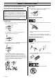
KEY TO SYMBOLS Symbols Only intended for trimmer heads. WARNING! Clearing saws, brushcutters and trimmers can be dangerous! Careless or incorrect use can result in serious or fatal injury to the operator or others. Please read the operator’s manual carefully and make sure you understand the instructions before using the machine. Other symbols/decals on the machine refer to special certification requirements for certain markets.
CONTENTS Contents KEY TO SYMBOLS Symbols ....................................................................... CONTENTS Contents ...................................................................... Note the following before starting: ................................ SAFETY INSTRUCTIONS Personal protective equipment ..................................... Machine′s safety equipment ........................................ Checking, maintaining and servicing the machine′s safety equipment ..................
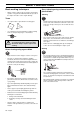
SAFETY INSTRUCTIONS Personal protective equipment IMPORTANT! Whenever you use a clearing saw, brushcutter or trimmer you must wear personal protective equipment that is approved by the authorities. Personal protective equipment does not eliminate the risk of accidents, but it can reduce the effects of an injury in the event of an accident. Ask your dealer for help when choosing protective equipment. ! WARNING! Listen out for warning signals or shouts when you are wearing hearing protection.
SAFETY INSTRUCTIONS Vibration damping system Your machine is equipped with a vibration damping system that is designed to minimise vibration and make operation easier. For mufflers it is very important that you follow the instructions on checking, maintaining and servicing your machine. See instructions under the heading Checking, maintaining and servicing the machine’s safety equipment. ! Use of incorrectly wound cord or an incorrect cutting attachment increases the level of vibration.
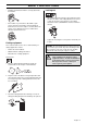
SAFETY INSTRUCTIONS Checking, maintaining and servicing the machine′s safety equipment IMPORTANT! All servicing and repair work on the machine requires special training. This is especially true of the machine′s safety equipment. If your machine fails any of the checks described below you must contact your service agent. When you buy any of our products we guarantee the availability of professional repairs and service.
SAFETY INSTRUCTIONS • • Regularly check that the muffler is securely attached to the machine. Locking nut • When fitting, tighten the nut in the opposite direction to the direction of rotation of the cutting attachment. To remove it, undo the nut in the same direction as the cutting attachment rotates. (CAUTION! The nut has a left-hand thread.) • Tighten the nut using the socket spanner. 35-50 Nm (3.55 kpm).
SAFETY INSTRUCTIONS Cutting equipment • IMPORTANT! This section describes how to choose and maintain your cutting equipment in order to: To increase the life of the cord it can be soaked in water for a couple of days. This will make the line tougher so that it lasts longer. IMPORTANT! Always ensure the trimmer cord is wound tightly and evenly around the drum, otherwise the machine will generate harmful vibration. Reduce the risk of kickback. Obtain maximum cutting performance.
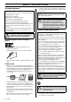
SAFETY INSTRUCTIONS • Never start the machine indoors. Exhaust fumes can be dangerous if inhaled. • Observe your surroundings and make sure that there is no risk of people or animals coming into contact with the cutting equipment. • • When storing the machine for long periods the fuel tank must be emptied. Contact your local gas station to find out where to dispose of excess fuel.
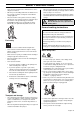
SAFETY INSTRUCTIONS Basic working techniques • Always slow the engine to idle speed after each working operation. Long periods at full throttle without any load on the engine can lead to serious engine damage. Grass trimming using a trimmer head and plastic blades Trimming Terms • Use a grass cutter or grass blade for clearing grass. • Use a trimmer head or plastic blades for lighter clearing work, for example along verges or around trees.
SAFETY INSTRUCTIONS Cutting • The trimmer is ideal for cutting grass that is difficult to reach using a normal lawn mower. Keep the cord parallel to the ground when cutting. Avoid pressing the trimmer head against the ground as this can ruin the lawn and damage the tool. • Do not allow the trimmer head to constantly come into contact with the ground during normal cutting. Constant contact of this type can cause damage and wear to the trimmer head.
WHAT IS WHAT? 30 29 28 27 17 What is what on the trimmer? 1 Trimmer head 16 Clutch cover 2 Grease filler cap 17 Handle adjustment 3 Bevel gear 18 Locking nut 4 Cutting attachment guard 19 Support flange 5 Shaft 20 Drive disc 6 Loop handle 21 Socket spanner 7 Throttle control 22 Operator’s manual (EPA) 8 Stop switch 23 Allen key 9 Throttle lock 24 Locking pin 10 Cylinder cover 25 Support cup 11 Starter handle 26 Blade 12 Fuel tank 27 Transport guard 13 Choke control 28 J
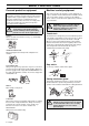
ASSEMBLY Fitting the loop handle Fitting the J-handle (GT 2125) (GC 2125) • Position the handle on the shaft. Note that the handle must be mounted below the arrow on the shaft. • Clip the loop handle onto the shaft. Note that the loop handle must be fitted between the arrows on the shaft. • Fit the screw, securing plate and wing nut as shown in the diagram. • Slide the spacer into the slot in the loop handle. • Tighten the wing nut. • Fit the nut, knob and screw. Do not overtighten.
ASSEMBLY Fitting blades and trimmer heads guard as possible. To tighten the nut, turn the spanner in the opposite direction to the direction of rotation (left-hand thread). When fitting the cutting attachment it is extremely important that the raised section on the drive disc/support flange engages correctly in the centre hole of the cutting attachment. If the cutting attachment is fitted incorrectly it can result in serious and/or fatal personal injury.
ASSEMBLY guard as possible. To tighten the nut, turn the spanner in the opposite direction to the direction of rotation (left-hand thread). Fitting the trimmer guard and trimmer head (GT 2125) Guard • ! Fit the guard as shown in the diagram. Tighten securely. WARNING! Grass blades or grass knives may only be used when the J-handle is fitted. Clearing blades must never be used with the J-handle.
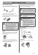
FUEL HANDLING Fuel Two-stroke oil CAUTION! The machine is equipped with a two-stroke engine and must always been run using a mixture of gasoline and two-stroke engine oil. It is important to accurately measure the amount of oil to be mixed to ensure that the correct mixture is obtained. When mixing small amounts of fuel, even small inaccuracies can drastically affect the ratio of the mixture.
FUEL HANDLING Fuelling ! WARNING! Taking the following precautions, will lessen the risk of fire: Do not smoke or place hot objects near fuel. Always shut off the engine before refuelling. Always stop the engine and let it cool for a few minutes before refuelling. When refuelling, open the fuel cap slowly so that any excess pressure is released gently. Tighten the fuel cap carefully after refuelling. Always move the machine away from the refuelling area before starting.
STARTING AND STOPPING Check before starting Starting and stopping For safety reasons follow these recommendations! • Check the blade to ensure that no cracks have formed at the bottom of the teeth or by the centre hole. The most common reason why cracks are formed is that sharp corners have been formed at the bottom of the teeth while sharpening or that the blade has been used with dull teeth. Discard a blade if cracks are found.
STARTING AND STOPPING Warm engine Starting Ignition: Set the stop switch to the start position. Choke: Set the throttle to the start position by moving the choke control to the choke position and then returning it to its original position. Hold the body of the machine on the ground using your left hand (CAUTION! Not with your foot!). Grip the starter handle, slowly pull out the cord with your right hand until you feel some resistance (the starter pawls grip), now quickly and powerfully pull the cord.
MAINTENANCE Carburettor Your Jonsered product has been designed and manufactured to specifications that reduce harmful exhaust fumes. The engine will be run in after it has used 8-10 tanks of fuel. To ensure that the engine runs at peak performance and produces as little harmful exhaust fumes as possible after the running-in period, ask your dealer/service workshop (which has a rev counter for this purpose) to adjust your carburettor. ! Rec. idle speed 2700 rpm Recommended max.
MAINTENANCE will run smoothly in every position. The idle speed should also be well below the speed at which the cutting attachment starts to rotate. Correctly adjusted carburettor When the carburettor is correctly adjusted the machine will accelerate without hesitation and burble a little at maximum speed. It is also important that the cutting attachment does not rotate at idle. If the low speed jet L is set too lean it may cause starting difficulties and poor acceleration.
MAINTENANCE Cooling system Air filter To keep the working temperature as low as possible the machine is equipped with a cooling system. The cooling system consists of: 1 Air intake on the starter. The air filter must be regularly cleaned to remove dust and dirt in order to avoid: 2 Fins on the flywheel. • Carburettor malfunctions 3 Cooling fins on the cylinder. • Starting problems 4 Cylinder cover (directs cold air over the cylinder).
MAINTENANCE Spark plug Weekly maintenance • Check the starter and starter cord. • Clean the outside of the carburettor. • Clean the outside of the spark plug. Remove it and check the electrode gap. Adjust the gap to 0.5 mm (.20”), or replace the spark plug. Check that the spark plug is fitted with a suppressor. • Clean the cooling fins on the cylinder and check that the air intake near the starter is not blocked.
TECHNICAL DATA Technical data Technical data GT 2125 GC 2125 1,50/24,5 1,50/24,5 Engine Cylinder volume, cu.in/cm3 Cylinder bore, inch/mm 1,26/32 1,26/32 Stroke, inch/mm 1,06/27 1,06/27 Idle speed, rpm 2700 2700 Recommended max. speed, rpm 11000-11700 11000-11700 Speed of output shaft, rpm 11700 8014 Max. engine output, acc.
TECHNICAL DATA Approved accessories Type Cutting attachment guard, Art. no.
FEDERAL EMISSION CONTROL WARRANTY STATEMENT YOUR WARRANTY RIGHTS AND OBLIGATIONS rights and responsibilities, you should contact your nearest authorized servicing dealer or call Jonsered, at Sweden +4636-146500 The EPA (The US Environmental Protection Agency), Environment Canada and Jonsered are pleased to explain the emissions control system warranty on your 2001 and later small nonroad engine. In U.S.
Trimmy H II 1 2 3 4 2,0-2,4 mm .080-.
S35 2 3 2,4-2,7 mm .095-.
S35 3 2 2,4-2,7 mm .095-.
Tap-N-Go 32 2 3 2,4-2,7 mm .095-.
Auto 32 1 2 3 4 2,4 mm .
1088893-95 ´®z*xyG¶5R¨ ´®z*xyG¶5R¨ 2003-04-07